Content last revised on September 10, 2026
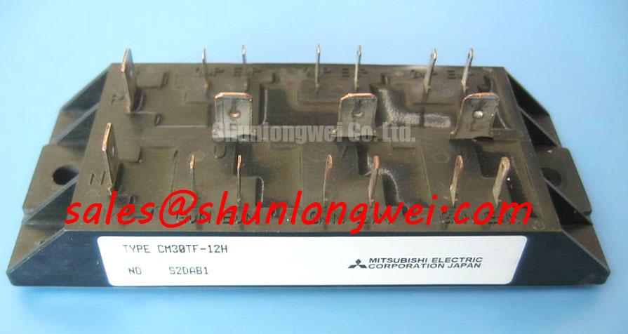
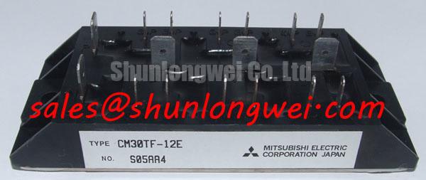
CM30TF-12E IGBT Module: 600V 30A Three-Phase Bridge Performance & Engineering Technical Overview
High-Density Power Switching for Industrial Inverters
Delivering Optimized Thermal Management and Low Conduction Loss in a Compact 6-Pack Architecture
Optimizing compact 3-phase inverter designs, the CM30TF-12E offers high power density with integrated super-fast recovery diodes for industrial motor control. Featuring key ratings of 600V VCES, 30A IC, and a low junction-to-case thermal resistance of Rth(j-c) = 0.80°C/W, this insulated module ensures minimal switching dissipation and simplified assembly with 2500Vrms isolation capability. By integrating a full six-IGBT bridge configuration, layout parasitics and heat sink requirements are minimized. For 230V/400V AC motor drives prioritizing compact inverter layouts, this 600V 30A module is the optimal choice.
Application Scenarios & Value
Achieving System-Level Reliability in Variable Frequency Drives and Industrial Automation
Engineers often face severe spatial constraints and parasitic inductance challenges when designing compact three-phase variable frequency drives (VFDs), servo amplifiers, and industrial uninterruptible power supplies (UPS). Incorporating discrete switches with antiparallel diodes increases printed circuit board complexity and localized thermal stress. The CM30TF-12E addresses these challenges by consolidating a complete six-switch bridge into a single thermally optimized package with an electrically isolated baseplate.
Operating efficiently under a maximum collector-emitter rating of 600V and continuous collector current of 30A, the module is well-suited for low-to-medium power motor drives, motion control units, and robotic servo drives. Its integrated design allows engineers to streamline thermal busbar routing while maintaining robust noise immunity across high-frequency pulse-width modulation (PWM) operational modes, supporting industry compliance with IEC motion control guidelines.
For systems requiring higher current handling capabilities or extended topology integration, related solutions such as the CM150DY-12H offer 150A current ratings, while modules like the CM300DU-12H provide dual-pack switching for larger motor systems, and the 7MBR50SA060 delivers integrated brake-rectifier-inverter functionality.
Technical & Design Deep Dive
Optimizing Collector-Emitter Saturation and Dynamic Switching Response
The internal architecture of the CM30TF-12E relies on planar gate silicon technology paired with discrete super-fast recovery free-wheel diodes. A central performance metric is the low collector-emitter saturation voltage, rated at VCE(sat) = 2.7V (typical) at IC = 30A and Tj = 25°C. Think of saturation voltage like internal fluid resistance: a lower VCE(sat) allows electric current to pass through the collector-emitter junction with reduced voltage drop, significantly lowering steady-state conduction losses during continuous high-load operations.
Thermal management is supported by a Direct Copper Bonding (DCB) ceramic substrate that ensures a low thermal resistance of Rth(j-c) = 0.80°C/W per IGBT chip. During high-frequency switching up to 20kHz, thermal heat generated in the silicon junctions is rapidly transferred to the cooling baseplate, expanding the device's Safe Operating Area (SOA). Designers should implement proper gate drive layout strategies, maintaining recommended gate resistance (RG) and negative gate voltage supply during turn-off to prevent parasitic Miller turn-on caused by rapid high dv/dt transients.
Key Parameter Overview
Decoding Core Specifications for Thermal and Electrical Design Verification
The technical parameters summarized below provide fundamental limits and operational metrics derived from official engineering specifications:
| Parameter | Symbol | Specification Value | Engineering Significance |
|---|---|---|---|
| Collector-Emitter Voltage | VCES | 600 V | Defines upper breakdown voltage margin for 230V/400V AC line applications. |
| Continuous Collector Current | IC | 30 A (TC = 25°C) | Determines continuous nominal phase current handling capacity. |
| Peak Collector Current | ICM | 60 A (Pulse width dependent) | Accommodates short-duration motor startup inrush current spikes. |
| Saturation Voltage | VCE(sat) | 2.7 V (Typ) / 3.5 V (Max) | Directly impacts conduction loss calculations in power stage efficiency models. |
| Junction Thermal Resistance | Rth(j-c) | 0.80 °C/W (Per IGBT) | Dictates heatsink sizing and thermal dissipation performance under continuous load. |
| Isolation Voltage | VISO | 2500 Vrms (AC 1 min) | Ensures safety compliance between power circuits and baseplate ground. |
Download the CM30TF-12E datasheet for detailed specifications and performance curves.
Frequently Asked Questions
Engineering Insights for Circuit Integration and System Protection
How does the 6-pack configuration of the CM30TF-12E simplify mechanical heat sink assembly?
By housing all six IGBT channels and anti-parallel diodes on a single isolated baseplate, the module requires only one unified mounting plane on the heatsink. This eliminates the thermal interface variations and mounting hardware complexity associated with multiple discrete TO-247 packages, streamlining production while maintaining consistent 2500Vrms electrical isolation.
Why is controlling gate resistor (RG) selection critical for the CM30TF-12E?
The gate resistor determines turn-on and turn-off switching speeds. Selecting an optimized RG balances switching losses (Eon/Eoff) against electromagnetic interference (EMI) and voltage overshoots caused by stray inductance. Proper sizing ensures stable operation without exceeding the module's reverse bias safe operating area (RBSOA).
What thermal management considerations apply when running the module at 15kHz to 20kHz PWM?
At higher PWM frequencies, switching losses contribute a larger portion of total power dissipation compared to conduction losses. Designers must calculate total losses (Ptotal = Pcond + Psw) and select heatsink performance based on the 0.80°C/W Rth(j-c) rating to ensure junction temperatures remain strictly within the -40°C to +150°C operating range.
How do the integrated free-wheel diodes protect the IGBT stage during inductive load switching?
The super-fast recovery antiparallel diodes provide a low-impedance freewheeling path for reactive energy stored in motor windings when the IGBT turns off. Their fast reverse recovery characteristics (trr ≈ 200ns) minimize reverse recovery current spikes and reduce turn-on energy losses in the opposing switch arm, aiding overall power stage durability in demanding motion control applications.
Balancing high switching efficiency with compact physical packaging remains a core design objective in modern power conversion. Incorporating robust semiconductor data into early stage hardware modeling enables engineering teams to accurately project thermal margins, optimize gate driver circuits, and achieve high system availability across industrial automation platforms.