


Content last revised on April 24, 2026
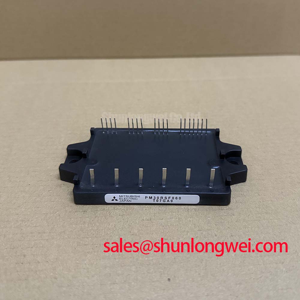
PM30RSF060 IPM: 600V/30A Integrated IGBT Module
An Intelligent Power Module for Streamlined Inverter Design
The Mitsubishi PM30RSF060 is an intelligent power module (IPM) engineered to consolidate the core functions of a three-phase inverter into a single, highly integrated package. It provides a robust foundation for compact and reliable motor control systems. By unifying the power stage, gate drive, and a full suite of protection circuits, this module significantly reduces design complexity and accelerates time-to-market. What is the primary benefit of this integrated approach? It is the drastic reduction in both component count and the engineering effort required to implement a dependable drive system.
- Core Specifications: 600V | 30A | VCE(sat) 2.2V (typ)
- Key Benefits: Simplified circuit design. Comprehensive built-in protection.
Deployment Archetypes: Maximizing System Value
While specific case studies are proprietary, the PM30RSF060 is architected for archetypal deployments where integration directly translates to competitive advantage. These include:
- Space-Constrained Commercial Appliances: In systems like commercial washing machines or HVAC fans, the module's compact footprint allows for smaller overall product dimensions without sacrificing power handling or reliability.
- High-Volume Industrial Automation: For manufacturers of small robotic arms or conveyor belt systems, the PM30RSF060's reduced component count and simplified assembly process can lead to significant reductions in manufacturing time and cost per unit.
- General-Purpose Low-Power Inverters: In applications up to approximately 1.5 kW, this IPM serves as a standardized power core, enabling engineering teams to develop a range of products from a single, pre-validated platform.
Engineering Crossroads: Evaluating the PM30RSF060
Selecting a power module involves weighing the benefits of integration against the flexibility of discrete components. The PM30RSF060 presents a clear value proposition for teams prioritizing design velocity and system-level reliability. The decision framework often involves assessing the total cost of ownership, which extends beyond the bill of materials.
Compared to a traditional solution using six discrete IGBTs, freewheeling diodes, gate drivers, and separate protection circuitry, this module offers a different engineering path. A discrete design provides granular control over component selection and layout but demands significant expertise in areas like gate drive optimization, parasitic inductance mitigation, and implementing robust fault detection. The PM30RSF060 pre-engineers these critical subsystems, shifting the design focus from the component level to the system level. For projects with tight deadlines or for teams without specialized power electronics resources, this streamlined approach is a decisive factor.
Anatomy of Integration: Inside the PM30RSF060
The core advantage of the PM30RSF060 lies in its high level of functional consolidation. It is more than just a collection of transistors; it is a cohesive power conversion subsystem.
Integrated Drive and Protection Circuitry
Within the module, each of the six IGBTs is paired with a dedicated gate drive circuit. This eliminates external driver components and the complex PCB layout they require. Crucially, the module also incorporates a suite of protective functions:
- Short-Circuit Protection (SC): Detects and safely shuts down the IGBTs in the event of a phase-to-phase or phase-to-ground short circuit.
- Over-Current Protection (OC): Monitors the collector current and initiates a soft shutdown if it exceeds a safe threshold.
- Over-Temperature Protection (OT): An integrated sensor monitors the module's substrate temperature and signals a fault if it surpasses the maximum limit.
- Control Supply Under-Voltage Lockout (UV): Ensures the gate drivers have sufficient voltage to keep the IGBTs fully enhanced, preventing operation in a high-dissipation linear region.
Upon triggering any of these protections, the module outputs a unified fault signal (Fo), simplifying error handling for the system's master controller. This comprehensive, built-in safety net is a critical aspect of its design simplification value. For a deeper understanding of fault prevention, see our guide on IGBT Failure Analysis.
Where Integration Accelerates Performance
The PM30RSF060 is optimized for power conversion applications where a balance of performance, size, and reliability is paramount. Its architecture is particularly well-suited for driving inductive loads, making it a strong candidate for a variety of motor control and inverter systems.
Its primary field of use is in three-phase inverters for AC motor control. This includes small Variable Frequency Drives (VFDs), servo drives for industrial automation, and the compressor motors found in air conditioning and refrigeration systems. The module's ability to handle 30A of continuous current at a case temperature of 100°C provides substantial capability for motors in the sub-2kW class. For systems that require higher current handling capacity, the BSM50GP60 offers a 600V, 50A alternative in a different package configuration. Due to its integrated protection and logic-level interface, the PM30RSF060 is an optimal choice for applications where reducing system complexity and improving long-term reliability are key design objectives.
The Strategic Value of Integrated Power Electronics
The move toward intelligent power modules like the PM30RSF060 reflects a broader industry trend: the increasing importance of system-level efficiency and accelerated development cycles. As market pressures demand faster innovation and lower lifetime costs, the value of pre-engineered, pre-validated power subsystems grows. By abstracting the complexity of the power electronics stage, IPMs allow engineering teams to allocate more resources to application-specific features, such as advanced control algorithms or user interface enhancements. This strategic shift from component-level design to system integration is fundamental to building next-generation, energy-efficient machinery and appliances.
PM30RSF060 Core Technical Specifications
This table highlights key performance parameters derived directly from the official datasheet. These values are essential for initial system-level analysis and thermal modeling.
| Parameter | Value |
|---|---|
| Collector-Emitter Voltage (VCES) | 600V |
| Collector Current (IC) @ Tc=100°C | 30A |
| Collector-Emitter Saturation Voltage (VCE(sat)) @ 30A, Tj=125°C | 2.2V (Typ.) / 2.7V (Max.) |
| Isolation Voltage (Viso) | 2500Vrms (1 minute) |
| Control Supply Voltage (VCC) | 15V (13.5V to 16.5V) |
| Short-Circuit Withstand Time (tsc) | >10µs |
Download the Datasheet for complete electrical characteristics and application notes.
Interpreting VCE(sat)
The Collector-Emitter Saturation Voltage, or VCE(sat), is a critical parameter for determining the module's efficiency. It represents the voltage drop across the IGBT when it is fully turned on. What is VCE(sat) in practical terms? Think of it like the friction inside a pipe; a lower friction value allows more water to flow with less pressure loss. Similarly, a lower VCE(sat) means less voltage is "lost" as heat when current flows through the device. The PM30RSF060's typical VCE(sat) of 2.2V at its nominal current dictates the conduction losses, a key factor in calculating the required heatsink size and overall system efficiency. For a deeper dive into this and other parameters, explore our guide on decoding IGBT datasheets.
Frequently Asked Questions
An Intelligent Power Module (IPM) like the PM30RSF060 includes not only the power semiconductor devices (IGBTs and diodes) but also the integrated gate drive circuits and a suite of protection features (over-current, short-circuit, etc.). A standard PIM typically only contains the power devices in a specific configuration (e.g., three-phase bridge), requiring an external gate driver and protection circuitry.
The module is designed for direct connection to microcontrollers and logic devices. Its inputs are high-active and compatible with 3.3V or 5V CMOS/TTL logic levels. It is crucial to ensure clean logic signals and respect the recommended dead-time between switching the high-side and low-side IGBTs of the same phase to prevent shoot-through. Always consult the datasheet's application notes for the recommended interface circuit, which typically includes a pull-down resistor.
In noisy industrial environments, it's a common challenge to maintain signal integrity. For the open-collector fault output, it is recommended to use a pull-up resistor (typically 4.7kΩ to 10kΩ) connected to a stable +5V supply. To improve noise immunity further, consider adding a small capacitor (e.g., 100pF) in parallel with the pull-up resistor to form a low-pass filter. This helps prevent spurious fault trips caused by transient noise.
Disclaimer: The technical information provided is based on publicly available datasheets. All operational parameters must be validated in your specific application. This content is for informational purposes only and does not constitute a commercial offer or guarantee of performance.