


Content last revised on September 30, 2026
Field Diagnostics & Commissioning: Galvanic Gate Drive Isolation in PM300CL1A060 Topologies
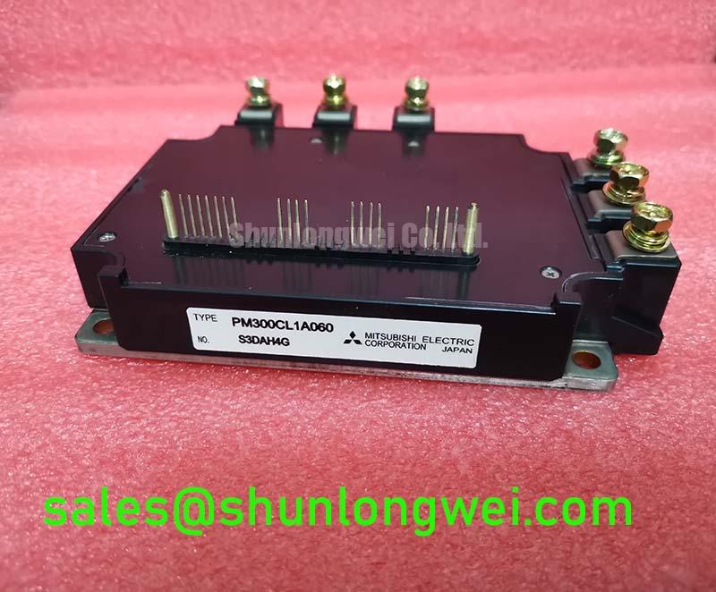
Measure the gate drive reference and power terminals with the inverter isolated, then compare resistance and continuity readings against an approved, known good assembly before applying DC link voltage. The PM300CL1A060 is identified here as a Mitsubishi Electric IPM module with a standard industrial rating and standard operating current; the original equipment documentation remains the controlling source for the exact voltage, current, control supply, terminal assignment, and protection limits.
For a commercial string inverter or microgrid energy storage converter, the first commissioning check is the galvanic boundary between the control board and the power stage. Inspect optocoupler or isolated gate driver supply paths, isolation slots, connector contamination, and any conductive residue around the control terminals. A low resistance reading across an intended isolation barrier requires isolation of the surrounding circuitry before drawing a conclusion, because parallel PCB components can influence the measurement.
Reinforced isolation and common mode transient immunity must be treated as system properties unless the applicable Mitsubishi Electric documentation explicitly assigns those values to this exact part number. Do not transfer a CMTI value or an isolation withstand rating from another IPM family. During an oscilloscope test, use an appropriately rated differential probe and verify that the probe, test fixture, and oscilloscope maintain the required isolation category. Observe gate to emitter behavior during both switching transitions and fault shutdown, paying attention to narrow pulses that are absent from the controller command.
Gate loop routing should keep the outgoing drive path and its return path close together, with the return referenced to the correct emitter or control reference defined by the original module documentation. Avoid routing a sensitive gate trace beside a high current commutation path. Minimize parasitic loop inductance to reduce induced gate disturbances, then verify the result through switching waveforms at the intended DC link, load current, and temperature conditions. Clearance and creepage are determined by the working voltage, pollution environment, insulation system, and applicable equipment standard, so the system engineer must establish those distances from the complete assembly specification.
Protection signals need the same measurement discipline. A fault output that remains active may be associated with overcurrent detection, undervoltage lockout, thermal protection, wiring error, or a fault elsewhere in the converter. Trace the signal from the IPM interface to the controller while recording supply behavior and fault timing. A single static continuity result cannot identify the cause. Check the controller command, isolated supply stability, gate waveform, DC link condition, and load response as separate observations.
The PM20CVL060-33 can be reviewed as a related Mitsubishi module reference during compatibility work, but a related part number is not a substitute approval. Compare terminal configuration, electrical ratings, protection behavior, mechanical dimensions, thermal interface, and control requirements before considering any cross reference.
Preventing Spurious Faults: Evaluating Thermal Capacitance vs Heat Sink Guidelines for PM300CL1A060
Record the module case temperature, heat sink temperature, load current, switching frequency, and fault timing during a controlled thermal test, then compare the trend with the known thermal limits for the complete PM300CL1A060 assembly. A transient overload cannot be assessed from heat sink temperature alone because the semiconductor junction responds faster than the external heat sink.
Thermal impedance is commonly represented with multiple resistance and capacitance sections so that short pulses, repeated pulses, and steady load can be considered separately. This is an engineering calculation method, not an additional Mitsubishi Electric specification. The calculated junction temperature should use the exact loss profile, duty cycle, case reference, mounting condition, and thermal data applicable to this module. When those inputs are unavailable, use waveform and temperature measurements to identify whether the result is suitable for further testing rather than assigning an assumed junction temperature margin.
Heavy pulsed operation requires attention to the recovery interval between events. A brief overload followed by a long cooling period has a different thermal response from a repeated pulse train with the same peak current. Review the pulse width, repetition pattern, conduction state, switching loss, diode recovery behavior, and heat sink airflow together. The module’s applicable transient current and temperature limits must come from the Mitsubishi Electric documentation for the exact device revision.
Dead time and gate interlock should be evaluated on both command channels at the module interface. Probe the high side and low side gate signals with channels that preserve the intended reference relationship, and inspect the interval during which both devices should be off. Excessive dead time can increase conduction loss and distortion, while insufficient dead time can permit cross conduction. The correct buffer is system determined by driver propagation delay, temperature drift, device switching behavior, layout parasitics, and the measured waveform.
Thermal faults can also be influenced by the heat sink interface. Inspect the baseplate contact pattern after a controlled installation check, and verify that the heat sink is flat, clean, and mechanically stable. Airflow obstructions, blocked channels, fan control faults, and enclosure recirculation can produce a thermal signature that resembles excessive module loss. Treat the thermal alarm, gate signal, phase current, and heat sink response as separate diagnostic channels.
Infineon’s CIPOS Intelligent Power Modules reference material provides useful industry context for integrated power module functions, but its electrical and thermal data must not be applied to the Mitsubishi Electric PM300CL1A060. Mitsubishi Electric’s CSTBT technology information is likewise manufacturer specific and should be used only for the device family to which it applies.
Benchtop Waveform Tuning: Mitigating Stress via Differential Gate Emitter Loop Routing to Emitter on PM300CL1A060
Capture the gate to emitter waveform directly at the PM300CL1A060 control interface while switching a controlled load, and compare it with the controller command at the same time reference. A gate waveform that looks clean at the driver output can show ringing or unintended movement at the module terminals because the physical return path carries common impedance and switching current coupling.
Use a compact differential measurement loop and keep the probe connection away from the high voltage commutation node. The emitter reference used by the driver should follow the terminal definition in the original Mitsubishi Electric documentation. Do not assume that a visually similar terminal on another module has the same electrical function. Separate the low level drive return from the high current power return where the module topology provides that distinction, while keeping the complete gate drive loop short and direct.
Mutual coupling becomes more significant when the main emitter path shares copper with a sensitive gate return. The resulting voltage movement can appear as gate oscillation, delayed turn off, or a narrow command-like pulse. These observations do not establish a single failure cause. Compare the waveform with the power stage disabled, with a resistive test load where appropriate, and with the final inductive load while recording DC link voltage and phase current.
During tuning, change one physical or electrical variable at a time and retain the original waveform for comparison. Review gate resistance, driver supply behavior, snubber condition, commutation loop geometry, connector inductance, and probe placement as separate factors. Any damping value is a typical starting point for bench evaluation, not a guaranteed PM300CL1A060 requirement. The final setting must be established from measured turn on and turn off behavior, switching loss, overshoot, thermal response, and fault performance.
Long motor cables and inverter output filters deserve specific attention when this module is evaluated in motor drive equipment. Cable impedance and termination can create reflected voltage at the motor terminals, while a filter can alter switching current and device loss. This behavior depends on cable construction, length, motor characteristics, switching pattern, filter topology, and grounding. Verify peak voltage at the relevant terminals with suitable high voltage differential measurement equipment rather than applying a generic multiplier to the DC link.
For commercial string inverter and microgrid storage equipment, the same principle applies to busbar symmetry and laminated interconnects. Keep the commutation path compact and balanced to reduce turn off overshoot, then validate peak voltage margins against the applicable device rating under worst case current, temperature, and control timing. Power quality requirements for phase controlled rectification and harmonic suppression belong to the complete converter design; the IPM alone cannot be represented as independently compliant with an EMC or grid standard.
Bench diagnostic: Disconnect power and allow the DC link to discharge before removing any control or power connector, then verify the absence of stored voltage with a properly rated meter.
Preventing Spurious Faults: Thermal Interface Material Thickness Uniformity Guidelines for PM300CL1A060
Inspect the thermal interface imprint across the PM300CL1A060 baseplate after a trial installation, because an uneven contact pattern can reveal heat sink flatness, mounting sequence, or interface material problems before full power testing. The material must cover the intended contact area without contaminating terminals, insulation features, or nearby control connections.
Thermal interface material thickness is an assembly parameter selected from the material specification, surface condition, module flatness, heat sink flatness, and required thermal resistance. A generic thickness range must not be presented as a Mitsubishi Electric specification for this model. The correct target should allow the material to fill surface irregularities without creating an unnecessarily thick thermal barrier. Excess material can also migrate under tightening force and leave dry regions elsewhere.
Baseplate curvature compensation is a mechanical design issue. Check the heat sink surface with suitable inspection equipment and remove burrs, particles, oxide flakes, and machining residue. The mounting surfaces should meet the equipment manufacturer’s flatness and finish requirements. If the contact imprint is concentrated at one edge, stop the power test and investigate the mechanical stack rather than compensating by adding more interface material.
Use the mounting hardware, washers, thread engagement, and tightening sequence specified for the actual Mitsubishi Electric package documentation. A sequential cross pattern is commonly used as a design consideration to distribute pressure, but the permitted torque and sequence are device and assembly specific. Tightening torque should be controlled with calibrated tools, and the module should not be forced into alignment by the screws.
After installation, measure thermal behavior at controlled load points and compare case temperature across phases where the topology permits. Unequal temperatures may reflect current imbalance, gate timing, airflow, sensor placement, or interface contact. Check the electrical and mechanical evidence together. A temperature difference by itself does not prove a defective module or an interface failure.
Maintain separation between the thermal installation process and the gate drive inspection. Interface compound, cleaning fluid, or metal debris near control terminals can affect insulation and signal integrity. Confirm that the heat sink, chassis, protective earth, and module isolation arrangement match the converter’s insulation design. Reinforced insulation, altitude performance, cosmic ray reliability, single event burnout, FIT data, and service life require authoritative device or system documentation; they should not be inferred from the package name or from generic IPM experience.
For long term evaluation, record the thermal cycle, load profile, ambient condition, fan state, and protection events in the test report. The article Evolution of Negative Off Bias Gate Drive Circuits may be used as a related engineering reference when reviewing turn off gate control, but its discussion does not establish a required bias voltage or lifetime result for PM300CL1A060. The final integration decision remains dependent on the original Mitsubishi Electric data and measured converter performance.