

Content last revised on January 31, 2026
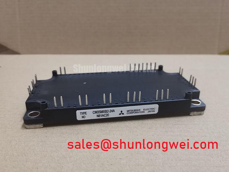
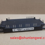
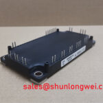
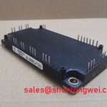
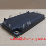
Mitsubishi CM35MXB2-24A CIB IGBT Module: Engineering Analysis
An Integrated Power Stage for Compact Motor Control Systems
The Mitsubishi CM35MXB2-24A is a highly integrated power module engineered to streamline the design of low-power motor control systems. Its core value lies in combining a full three-phase converter, a three-phase inverter, and a brake chopper into a single compact package. With specifications of 1200V | 35A | CIB Topology, this module delivers significant engineering benefits, including a drastically reduced component count and simplified assembly processes. It directly addresses the challenge of fitting comprehensive drive functionality into space-constrained industrial enclosures. For low-power AC drive designs where space, assembly cost, and braking capability are critical design drivers, the CM35MXB2-24A offers an optimized, all-in-one power stage solution.
Application Scenarios & Value
System-Level Benefits in AC Motor and Servo Drives
The primary value of the CM35MXB2-24A is unlocked in applications demanding high functional density. This module is an ideal power core for general-purpose AC inverters, vector drives, and servo amplifiers, typically in the sub-15 kW power range. A high-fidelity engineering scenario is the development of a compact variable frequency drive (VFD) for a conveyor belt system. In this application, frequent start-stop cycles and rapid deceleration are common. The integrated brake chopper in the CM35MXB2-24A becomes critical, as it efficiently dissipates regenerative energy from the motor during braking without requiring a separate, bulky external braking unit. This integration not only saves valuable DIN rail or panel space but also simplifies wiring, reduces assembly time, and minimizes potential EMI loops associated with connecting an external chopper. This module's all-in-one nature fundamentally accelerates the design-to-production lifecycle for compact drive systems. For systems that demand higher power output while maintaining a similar integrated topology, the CM50DY-24H provides a higher current rating within the same voltage class.
Key Parameter Overview
Decoding the Specs for Integrated Drive Design
The specifications of the CM35MXB2-24A are best understood when grouped by their function within the integrated CIB (Converter-Inverter-Brake) architecture. This approach allows engineers to evaluate the performance of each section relative to their specific application requirements.
| Parameter | Value | Conditions |
|---|---|---|
| Inverter Section (per IGBT) | ||
| Collector-Emitter Voltage (VCES) | 1200V | - |
| Collector Current (IC) | 35A | TC = 25°C |
| Collector-Emitter Saturation Voltage (VCE(sat)) | 2.25V (Typ.) / 2.7V (Max.) | IC = 35A, VGE = 15V |
| Thermal Resistance (Rth(j-c)) | 0.42°C/W | Per IGBT |
| Converter & Brake Section | ||
| Repetitive Peak Reverse Voltage (VRRM) - Converter Diode | 1600V | - |
| Forward Current (IF(AV)) - Converter Diode | 35A | - |
| Collector Current (IC) - Brake IGBT | 35A | TC = 25°C |
| General Module Characteristics | ||
| Isolation Voltage (Visol) | 2500Vrms | AC, 1 minute |
| NTC Thermistor | Yes | Integrated for temperature monitoring |
Download the CM35MXB2-24A datasheet for detailed specifications and performance curves.
Frequently Asked Questions
How does the integrated CIB topology of the CM35MXB2-24A impact the system's bill of materials (BOM) and reliability?
The CIB (Converter-Inverter-Brake) topology consolidates the AC-DC rectifier, DC-AC inverter, and braking chopper into a single component. This dramatically simplifies the BOM by eliminating the need to source, qualify, and assemble separate rectifier bridges and brake chopper modules. Fewer discrete components and interconnections lead to a more reliable system with fewer potential points of failure, such as solder joints or crimped connections.
What is the engineering significance of the 2.25V typical VCE(sat) at the nominal 35A rating?
The Collector-Emitter Saturation Voltage (VCE(sat)) is the primary source of conduction loss when the IGBT is on. A VCE(sat) of 2.25V at 35A means that for every moment the inverter's IGBT is conducting its full rated current, it generates approximately 78.75 watts (P = V * I) of heat. Understanding this value is fundamental for thermal design; it directly dictates the size and performance requirements of the heatsink needed to keep the module's junction temperature within its Safe Operating Area (SOA) under worst-case load conditions.
What is the function of the integrated NTC thermistor and how should it be used in a drive design?
The integrated NTC (Negative Temperature Coefficient) thermistor provides a real-time method for monitoring the module's internal baseplate temperature. In a drive design, the thermistor's output should be connected to the control board's analog input. This allows the drive's firmware to implement critical protection features. For example, it can trigger a fault and safely shut down the drive if the temperature exceeds safe limits, preventing thermal runaway and catastrophic failure. It also enables intelligent fan control and can be used to de-rate the drive's output power gracefully in over-temperature conditions, enhancing overall system robustness.
Engineer's Perspective
From a design engineering standpoint, the CM35MXB2-24A is less about pushing a single performance metric to its limit and more about providing a balanced, highly practical solution for a specific problem: the efficient construction of compact motor drives. The choice to use this module is a strategic one, trading the granular component selection of a discrete design for the significant benefits of integration. This approach accelerates development, simplifies manufacturing, and can improve field reliability by using a pre-qualified, factory-tested power stage. For engineering teams focused on time-to-market and total cost of ownership for low-power drive applications, this module represents a compelling and efficient building block.