
Content last revised on September 26, 2026
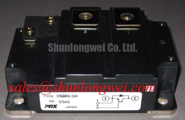
CM600HU-24H Identification and Service Ratings
With the converter isolated and its DC link verified discharged, measure the cold-state resistance between the main terminals of the removed CM600HU-24H and compare the readings with the equipment’s documented service checks. Record any visible damage and confirm the module label before disturbing the busbars. A resistance reading alone cannot establish whether an IGBT will switch correctly under load, but it can help prioritize the next bench tests.
The Mitsubishi Electric CM600HU-24H is an IGBT module rated for 1200 V collector-to-emitter voltage and 600 A continuous collector current at a case temperature of 25°C. Those are Official Specification values, not a promise that an existing converter will deliver that current after installation. The equipment’s cooling, gate drive, protection circuit and operating duty determine the usable operating point.
| Parameter | Official Specification | Service relevance |
|---|---|---|
| Collector-to-emitter voltage, VCES | 1200 V | Compare with the measured DC link and switching transients. |
| Continuous collector current, IC | 600 A at TC = 25°C | Check the actual case-temperature and duty conditions. |
| Peak collector current, ICM | 1200 A | Review transient loading against the equipment’s protection scheme. |
| Maximum collector dissipation, PC | 3100 W at TC = 25°C | Assess losses and heat removal at the intended operating point. |
| Isolation voltage, Viso | 2500 Vrms, AC for 1 minute | Use the stated test rating in the equipment-level insulation review. |
| Junction temperature range, Tj | −40°C to +150°C | Verify thermal limits under operating and transient conditions. |
| Main power terminals | M8 screws; 9.8 to 10.8 N·m tightening torque | Check busbar seating and apply the specified terminal torque. |
Benchtop Waveform Tuning: Desaturation Detection on CM600HU-24H
Before energizing a repaired converter, trace the gate-driver fault path from its desaturation input to the command that turns the IGBT off. A rising collector-to-emitter voltage while the device is commanded on can indicate a short-circuit condition, but the driver must distinguish a genuine fault from the normal voltage present during turn-on. For the CM600HU-24H, the supplied module ratings do not specify a complete short-circuit withstand time or a required desaturation response interval. Detection timing therefore belongs to the validated driver and converter design; it should not be inferred from the 1200 A peak-current rating.
On the bench, capture the gate command, gate-to-emitter voltage, desaturation signal and collector voltage with measurement methods appropriate to the equipment’s voltage. Compare their order of events with the original driver documentation. If a fault appears only at turn-on, inspect blanking behavior and the desaturation sensing path before treating the module as the sole cause. If it appears after current has risen, examine both the load path and the driver response. A staged or soft turn-off is a Design Consideration where abrupt fault-current interruption would produce excessive inductive overshoot; its timing must be confirmed by switching tests within the system’s protection limits.
For a replacement assessment, match the physical terminals, mounting interface and original circuit requirements rather than selecting by current rating alone. The CM100DY-12E is a separate Mitsubishi Electric module to compare when reviewing topology options, not an established drop-in substitute for the CM600HU-24H. Its electrical ratings and terminal arrangement require an independent check against the equipment drawings.
Benchtop Waveform Tuning: PCB Gate Loop Layout on CM600HU-24H
Follow the gate-drive return conductor on the schematic and on the physical assembly. Current through a shared power-emitter path can disturb the voltage seen by the driver and contribute to unwanted gate movement. As a Design Consideration, keep the gate-drive loop compact and separate its return from high-current busbar paths where the module’s documented terminals and the existing assembly permit it. Do not assume a dedicated Kelvin emitter terminal without confirming the terminal diagram for the exact module and installation.
When a scope trace shows gate ringing, first verify probe placement and the driver supply under load. Then compare gate-to-emitter behavior during turn-on, turn-off and fault handling with a known-good channel, if one is available. Inspect return routing, connector seating and local driver decoupling before changing a gate resistor. A resistor adjustment may quiet a trace while also changing switching loss or fault turn-off behavior; the converter designer should validate both effects at the intended operating conditions.
If the equipment uses a bootstrap supply for a high-side driver, capacitor selection is a driver-design task rather than a CM600HU-24H module rating. The Design Consideration is to account for the gate charge demanded by the switching cycle, driver quiescent consumption and allowable supply-voltage droop, then verify the supply at the actual duty pattern. The module information supplied here gives no gate-charge figure, so a capacitor value cannot be responsibly calculated from it.
The same distinction matters when modules are paralleled. Their static current sharing depends on device characteristics and thermal conditions; dynamic sharing also depends on gate-drive timing and the symmetry of the power and gate paths. Do not assume that a favorable temperature coefficient alone will equalize switching current. Measure each branch under the converter’s operating conditions and assess both conduction and transition waveforms.
Transient Dynamics and Electrical Design: Turn-Off Voltage Clamping on CM600HU-24H
Measure collector-to-emitter voltage at turn-off before deciding whether an apparent overvoltage is a device issue, a probing artifact or a busbar-layout problem. The peak includes the DC-link voltage plus the contribution from stray inductance as current changes; faster current interruption or greater loop inductance can raise that peak. The 1200 V VCES Official Specification is the boundary to check against the measured waveform, while the allowable operating margin and test conditions must come from the converter design.
A snubber or clamp can be evaluated as a Design Consideration when measured peaks approach the equipment’s permitted limit. Its capacitor and associated components must be selected against the observed pulse energy, repetition rate and thermal loading, not from the module current rating alone. Keep opposing DC-link paths close and examine the symmetry of busbar connections to reduce parasitic inductance. No universal busbar-inductance target follows from the supplied CM600HU-24H specifications; confirm the finished assembly by measurement.
On a regenerative drive, inspect the braking chopper and resistor path as well as the IGBT waveform. A braking resistor dissipates energy directed to it by the system controls; an open path, incorrect control action or changed duty can alter DC-link behavior and the stress seen during switching. For a wind-turbine full-scale converter, this is a compatibility and fault-finding check, not an assumption that the CM600HU-24H occupies a particular chopper or inverter position. Confirm its actual circuit location from the equipment drawings.
Mechanical and thermal contact deserve a separate check after electrical measurements. Inspect the heatsink contact surface, apply thermal interface material according to the equipment assembly procedure and tighten the M8 main power terminals to 9.8 to 10.8 N·m, the supplied Official Specification. The 3100 W maximum collector-dissipation figure is specified at TC = 25°C; it is not a continuous loss allowance at an arbitrary installed case temperature. Where a system uses heat-pipe cooling, the heat-pipe phase-change principle explains heat transport, but the complete cooler still needs verification against measured module temperatures.
Field Alert: Keep thermal interface material off the power-terminal contact faces, then verify busbar seating before applying the specified M8 terminal torque.
Preventing Spurious Faults: Altitude and Cosmic-Ray Evaluation for CM600HU-24H
Do not label an intermittent converter trip as radiation-induced device failure because it occurred at altitude. First collect the fault code, DC-link trend, gate-driver status and switching waveform, then check cooling, connections and protection timing against the equipment records. Those observations can separate a repeatable electrical fault from a trip that remains unexplained; they cannot, by themselves, establish a single-event burnout mechanism.
Altitude-related operating limits and terrestrial-neutron effects are Design Considerations for the complete power system. The supplied CM600HU-24H specifications provide no altitude derating curve, cosmic-ray failure rate or failure-in-time value. Consequently, no numerical SEB risk or service-life prediction can be assigned to this installation from these ratings. A system assessment should use applicable manufacturer reliability information and the actual DC-link voltage, site conditions and protection architecture. The Power Electronics Masterclass provides broader context for that reliability review without replacing equipment-specific validation.
When a high-altitude unit repeatedly reports overvoltage or desaturation, compare event timing with measured DC-link and gate-driver behavior before changing a voltage setting. Preserve the original fault records, verify the cooler and terminal joints, and review switching peaks against the module’s 1200 V rating. Any revised operating limit must be established by the system engineer using evidence for the installed converter.