

Content last revised on March 9, 2026
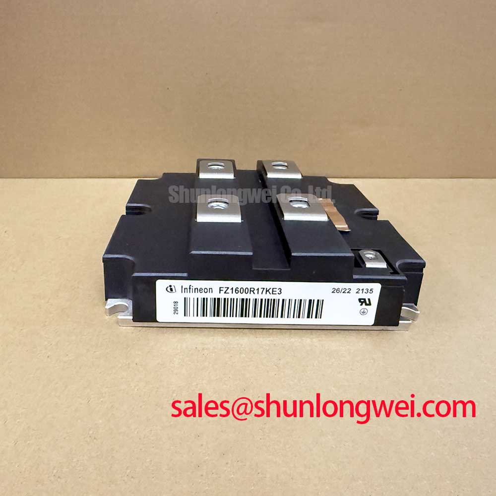
FZ1600R17KE3 Infineon 1700V 1600A Single Switch IGBT Module: Engineering Deep Dive
Highlights & Engineering Overview
Maximizing Power Density in Mega-Watt Class Inverter Topologies
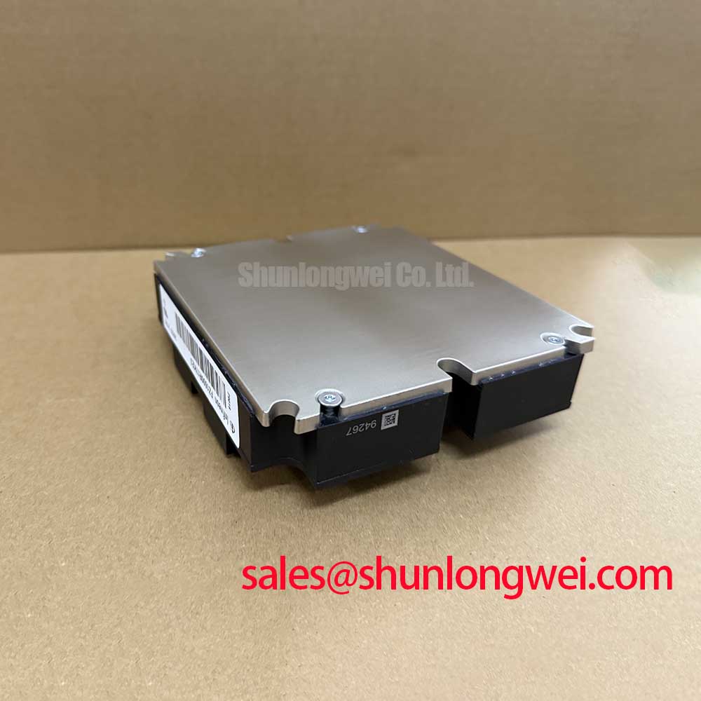
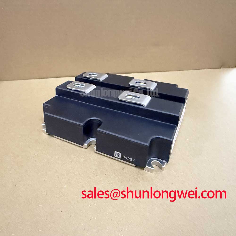
How can engineers maintain high thermal stability while switching massive current loads exceeding 1500A in a single-switch configuration? The FZ1600R17KE3, a high-power IGBT Module manufactured by Infineon, addresses this challenge through its advanced TRENCHSTOP™ IGBT3 silicon and EmCon 3 diode technology. With a maximum collector-emitter voltage of 1700V and a continuous DC collector current of 1600A, this module serves as a cornerstone for high-efficiency power conversion. What is the primary benefit of its IHM-B package design? It ensures high power density and ruggedness by providing a low-inductance terminal layout and optimized thermal paths. For utility-scale wind central inverters requiring 1700V isolation and 1.6kA throughput, the FZ1600R17KE3 offers the optimal balance of power density and thermal robustness.
Frequently Asked Questions
Addressing Critical Design Challenges in High-Current Power Electronics
How does the low Vce(sat) of the FZ1600R17KE3 impact overall system efficiency in continuous operation?
The FZ1600R17KE3 features a low collector-emitter saturation voltage (typically 2.00V at 1600A), which acts like a low-resistance "toll booth" on a high-speed highway. By reducing the "toll" (voltage drop), the module significantly minimizes conduction losses during the "on" state. For high-power systems like grid-tie solar inverters, this translates to lower heat generation, allowing for smaller cooling systems and higher overall energy yield.
What is the engineering significance of the 10µs short-circuit withstand time for system safety?
The FZ1600R17KE3 is rated for a 10µs short-circuit withstand time at 125°C. This parameter provides a critical safety buffer for the gate drive protection circuitry to detect a fault condition and safely shut down the module before catastrophic failure occurs. In variable frequency drive (VFD) applications, this ruggedness is essential for surviving unexpected motor stalls or cable insulation breakdowns.
Key Technical Parameter Overview
Decoding Specifications for Enhanced System Reliability
The following technical specifications are derived from official manufacturer data for the FZ1600R17KE3. These parameters are vital for defining the Safe Operating Area (SOA) and thermal management strategies.
| Specification Parameter | Technical Value | Engineering Interpretation |
|---|---|---|
| Collector-Emitter Voltage (Vces) | 1700V | Ideal for 690V AC line voltages with ample overhead for switching transients. |
| Continuous DC Collector Current (Ic) | 1600A (at Tc=80°C) | Enables high-current output in single-switch or parallel configurations. |
| Repetitive Peak Collector Current (Icrm) | 3200A | Provides peak current handling for motor starting surges and pulsed loads. |
| Vce(sat) (Tvj=125°C, Ic=1600A) | 2.40V (Max) | Lower conduction losses, simplifying Thermal Management in dense cabinets. |
| Short-Circuit Withstand Time (tp) | 10µs | Sufficient duration for desaturation protection to trigger safely. |
| Thermal Resistance (Rthjc) - IGBT | 0.012 K/W | Extremely low thermal path from junction to case for maximum heat extraction. |
Download the FZ1600R17KE3 datasheet for detailed specifications and performance curves.
Industry Insights & Strategic Advantage
The Future of High-Power Switching in Renewable Energy Infrastructure
As the global energy transition accelerates, the demand for high-reliability components like the FZ1600R17KE3 has shifted from traditional industrial motor control to utility-scale renewable infrastructure. The integration of TRENCHSTOP™ IGBT3 technology ensures that these modules can handle the fluctuating duty cycles common in wind and solar power generation. Furthermore, the adoption of advanced IHM-B packaging materials enhances the power cycling capability, which is critical for systems with 20+ year expected lifespans. For engineers seeking to understand the underlying physics of these transitions, our resource on an in-depth analysis of IGBT modules provides further context. Strategically, utilizing high-current single switches simplifies the busbar design and reduces the complexity of IGBT paralleling, leading to higher system-level reliability in accordance with IEC 61800-3 standards.
Application Scenarios & Value
Achieving Reliability in Harsh Industrial and Utility Environments
The FZ1600R17KE3 is specifically engineered for high-stakes power conversion scenarios where downtime results in significant financial loss. In wind central inverters, the module manages the output of multi-megawatt turbines, converting variable frequency energy to stable grid power. The module's low thermal resistance (Rthjc) of 0.012 K/W allows it to maintain a lower junction temperature even under full load, which exponentially increases the component's lifespan. To understand how this fits into your cooling strategy, refer to our guide on Why Rth Matters.
Beyond renewables, this module is a staple in uninterruptible power supplies (UPS) for data centers and high-power traction drives. For designs that require similar voltage ratings but lower current throughput, the FZ400R17KE3 offers a 400A alternative in a smaller footprint. Conversely, for ultra-high power systems requiring even higher density, the FZ2400R17KE3_S1 provides an expanded 2400A current rating.
Additional Technical Considerations
Optimizing the Gate Drive and Thermal Interface
Does the IHM-B package support press-fit or solder pins for the auxiliary terminals?
The FZ1600R17KE3 typically utilizes standard solderable auxiliary pins for control signals. This design ensures mechanical stability against vibrations found in traction applications. Engineers must ensure a robust Thermal Management plan, utilizing high-performance thermal interface materials (TIM) to bridge the 0.012 K/W IGBT junction-to-case resistance to the ambient environment.
How can I mitigate Miller effect turn-on in a high-current environment like the 1.6kA switch?
With the high currents managed by the FZ1600R17KE3, stray inductances and high dV/dt can lead to parasitic turn-on. Implementing a Miller Clamp in the gate driver circuit is a standard practice to keep the gate voltage low during switching transients, preventing cross-conduction in half-bridge configurations.
In the landscape of high-power semiconductor technology, the FZ1600R17KE3 remains a definitive solution for engineers prioritizing long-term field reliability and thermal efficiency. By leveraging the TRENCHSTOP™ IGBT3 architecture, Infineon has provided a path for high-power density designs that meet the rigorous demands of modern IGBT Module applications.