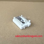
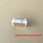
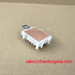
Content last revised on October 23, 2026
FS15R06VE3_B2 Identification and Pre-Power Repair Checks
- With the DC link discharged and absence of voltage verified, compare unpowered terminal measurements against the circuit diagram and a known-good phase.
- Inspect the heatsink contact surface, mounting hardware, and module seating for contamination, distortion, or uneven contact.
- Check gate-driver auxiliary supplies, shutdown interlocks, and gate connections before enabling the power stage.
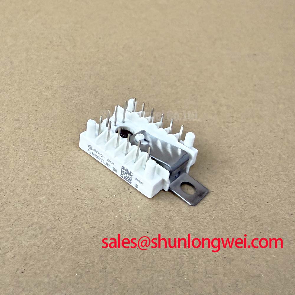
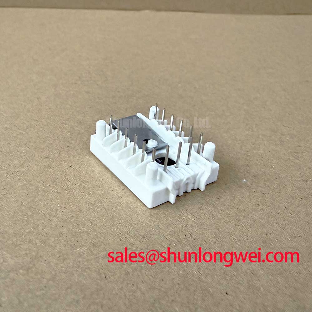
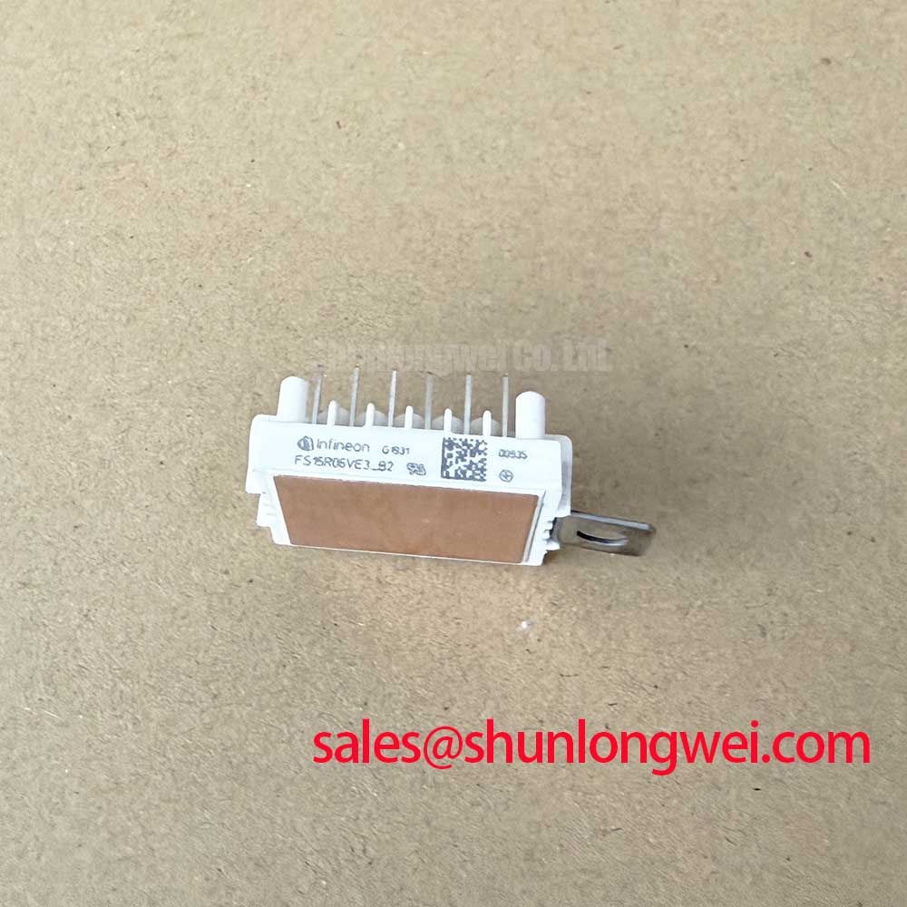
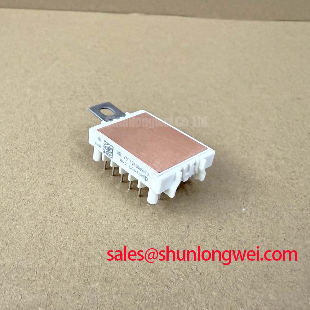
- Match the complete FS15R06VE3_B2 designation to the equipment parts list, including the suffix and terminal arrangement.
The Infineon FS15R06VE3_B2 IGBT module has a 600 V collector-emitter rating and a specified continuous collector current of 15 A at a case temperature of 80°C. For repair assessment, these electrical limits belong alongside the mechanical interface, driver configuration, cooling arrangement, and protection settings. Matching voltage and current alone does not establish interchangeability.
The following official specifications identify the principal electrical boundaries and monitoring interface. Consult the manufacturer’s datasheet for terminal assignments, mounting instructions, characteristic curves, and additional test conditions.
| Functional group | Parameter | Official Specification |
|---|---|---|
| IGBT inverter | Collector-emitter voltage, VCES | 600 V |
| IGBT inverter | Continuous DC collector current, IC | 15 A at TC = 80°C |
| IGBT inverter | Collector-emitter saturation voltage, VCE(sat) | 1.55 V at Tvj = 125°C |
| Diode inverter | Repetitive peak reverse voltage, VRRM | 600 V |
| Diode inverter | Forward voltage, VF | 1.60 V at Tvj = 125°C |
| Temperature monitoring | NTC thermistor resistance | 5 kΩ at 25°C |
| Isolation test | Isolation test voltage, Visol | 2.5 kV RMS, 50 Hz, 1 minute |
Preventing Spurious Faults: Mounting and Substrate Protection Guidelines for FS15R06VE3_B2
Inspect heatsink flatness and the module’s mating surface before tightening the mounting hardware. Raised debris, machining burrs, or displaced interface material can concentrate pressure and compromise thermal contact. As a Design Consideration, assess contact geometry against the applicable assembly drawing rather than assuming that every mating surface should be perfectly flat; any specified curvature belongs to the mechanical design and should not be corrected by improvised machining.
Seat the module without using the screws to pull a misaligned assembly into position. Where the mounting instructions permit staged cross-pattern tightening, a calibrated tool helps distribute clamping pressure progressively. The specified fastener, tightening sequence, and torque must come from the relevant mounting documentation. Neither a generic screw-size torque nor additional tightening after warm-up establishes an acceptable installation.
Thermal interface material should provide continuous contact without becoming a substitute for correcting poor surface condition. As an Engineering Recommendation, use the approved material and application method, then assess coverage during assembly qualification. Avoid assigning a universal film thickness to this module: contact pressure, material properties, surface geometry, and the manufacturer’s mounting instructions determine the appropriate process. Likewise, substrate composition and baseplate material should not be inferred from the product designation.
The integrated 5 kΩ NTC at 25°C provides a temperature-dependent resistance for the monitoring circuit. Check its wiring, connector continuity, and measurement-channel behavior when investigating thermal trips. Its reading does not directly reproduce instantaneous semiconductor junction temperature; the thermal path and operating transient affect that relationship. A drifting temperature indication can therefore justify checking the sensor circuit and heatsink contact before changing protection thresholds.
For compatibility assessment, the FB15R06KL4_B1 can serve as a comparison reference, not an automatic replacement recommendation. Compare circuit configuration, terminal positions, mounting geometry, driver requirements, and thermal characteristics independently. Engineers evaluating light industrial automation or multi-joint robotic actuator drives should also check the original equipment’s acceleration, braking, and enclosure-cooling requirements before accepting a replacement configuration.
Transient Dynamics and Electrical Design: Gate-Driver Auxiliary Power Sequencing for FS15R06VE3_B2
Establish valid gate-driver auxiliary supplies and a defined shutdown state before allowing the DC link to energize. As a Design Consideration, the startup logic should inhibit switching while the driver supply is below its valid operating range and preserve a controlled off state during supply collapse. Check this behavior at the gate-driver output, not only at the controller’s enable signal.
A negative turn-off bias is a system-level driver choice, not a requirement established by the electrical ratings above. If the existing design uses it, verify the complete gate-voltage excursion against the module’s allowable gate-emitter limits, including switching transients. Miller-induced gate movement depends on collector-voltage transition rate, gate-loop impedance, and the driver’s sink behavior. Keep the gate return closely associated with its drive path and evaluate the off-state waveform under representative switching conditions.
Optocoupler and digital-isolator selection also affects command integrity. As an Engineering Recommendation, compare the isolator’s common-mode transient immunity conditions with measured switching-node transitions and the actual isolation-barrier layout. An apparent extra pulse may originate in the command path, driver supply disturbance, or measurement setup; correlate input, output, and gate waveforms before attributing it to the power module.
Practical tip: Keep the commutation path compact and geometrically balanced, then use controlled double-pulse testing to check turn-off voltage overshoot against the module rating.
The 600 V blocking rating must accommodate the collector-emitter voltage actually reached during operation, including transients. As a Design Consideration, an MOV-based absorption network requires coordination with its installation point, clamping behavior, energy capability, and connecting inductance. A suppressor elsewhere in the cabinet does not necessarily control a fast local switching peak. Measure the waveform at the relevant power terminals and let those results guide system-level suppression choices.
For semiconductor behavior and terminology, Infineon’s IGBT Discretes & Co-Pack Diodes resources provide manufacturer context without replacing this module’s documentation. Its OptiMOS™ and CoolMOS™ Power MOSFET resources address a different device family; MOSFET drive practices and switching characteristics should not be transferred unchanged to this IGBT module.
Assembly Integrity and Layout Architecture: Short-Circuit Energy Coordination for FS15R06VE3_B2
Coordinate the gate-driver fault response and the upstream protective device as separate protection functions. Driver shutdown addresses semiconductor fault stress, while a fuse interrupts the prospective circuit fault according to its own operating characteristics. As a Design Consideration, fuse total-clearing I²t is relevant to coordination, but it is not interchangeable with an IGBT short-circuit withstand time or a diode surge-current rating.
Evaluate fuse behavior at the actual DC-link voltage, prospective fault current, circuit time constant, and available stored energy. The interruption capability must suit the circuit, and the driver’s detection delay and controlled turn-off behavior must be assessed separately. Selecting a fast fuse alone does not establish that the module will survive a fault or that enclosure rupture is excluded. Protection validation should follow the equipment’s controlled test and containment procedures.
The listed diode reverse-voltage and forward-voltage values do not establish a repetitive surge allowance or an ITSM limit. After an abnormal current event, a reset decision should account for the thermal state and the reason protection operated, rather than relying on a fixed recovery delay. The 1.60 V diode forward-voltage value at 125°C is a characteristic point, not a complete surge-energy model.
Parallel-module operation requires similar care. As a Design Consideration, a single saturation-voltage value does not establish a positive temperature coefficient across the operating range or guarantee current sharing. Static sharing depends on device characteristics and thermal balance; dynamic sharing also depends on gate timing and power-path impedance. Evaluate both before treating parallel branches as a higher-current equivalent.
When reviewing an upstream rectifier, DC link, and inverter together, document each stage’s function explicitly. The FS35R12YT3 is a separate power-module reference for complementary-stage assessment, not an assumed input rectifier or a prescribed companion to this part. Circuit topology, control requirements, and electrical interfaces determine whether it belongs in the same equipment architecture.
The 2.5 kV RMS isolation test for one minute at 50 Hz describes a specified test condition, not a continuous working-voltage allowance or an equipment safety approval. Maintain the assembly’s required clearances and insulation arrangements during repair. For structured fault records and repeatable measurement practices, the Field Engineer’s Handbook provides supporting guidance; record the module identity, thermal-contact observations, driver sequencing, and protection waveforms so the repaired assembly can be assessed against its original acceptance criteria.