


Content last revised on March 28, 2026
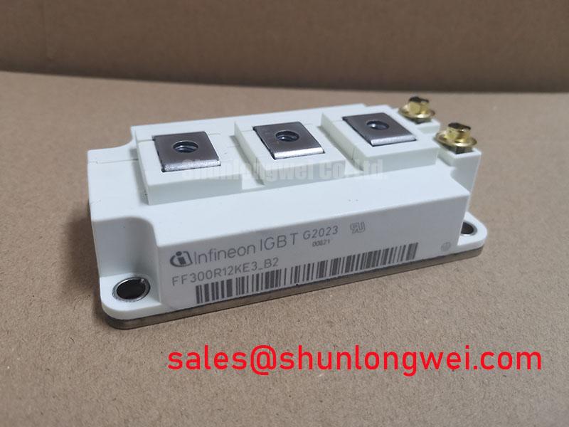
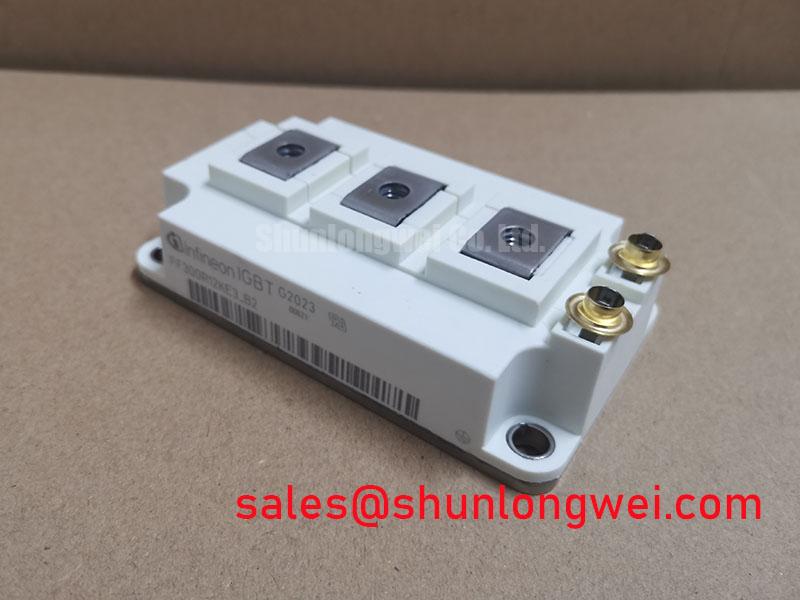
Infineon FF300R12KE3_B2: Master High-Efficiency Power Conversion with IGBT3 Technology
At the heart of modern, high-efficiency power conversion systems lies a critical choice: the power switching component. The Infineon FF300R12KE3_B2, a 1200V, 300A dual IGBT module, is engineered around the proven TRENCHSTOP™ IGBT3 technology. This technology represents a pivotal moment in power electronics, delivering exceptionally low collector-emitter saturation voltage (VCE(sat)). Think of VCE(sat) as the 'friction' a current experiences when flowing through the switch. The FF300R12KE3_B2 minimizes this friction, which directly translates into lower conduction losses and reduced heat generation. This fundamental characteristic makes it a cornerstone for applications where operational efficiency and thermal stability are paramount, particularly in systems operating at low to medium switching frequencies. By leveraging this mature yet powerful technology, designers can achieve superior performance and reliability without the complexities of higher-speed chip generations.
Frequently Asked Questions (FAQ)
What is the key difference between the FF300R12KE3_B2 (IGBT3) and the FF300R12KE4?
The primary difference lies in the IGBT chip generation and its resulting trade-offs. The FF300R12KE3_B2 uses TRENCHSTOP™ IGBT3 technology, which is optimized for the lowest possible conduction losses (VCE(sat)). In contrast, the FF300R12KE4 employs the next-generation IGBT4 technology, which focuses on reducing switching losses. For applications like motor drives that operate at lower frequencies, the KE3's lower conduction losses are more beneficial. For higher-frequency applications like solar inverters or UPS, the KE4's lower switching losses would be advantageous.
Is the emitter-controlled diode in the FF300R12KE3_B2 suitable for high-frequency resonant topologies?
The included emitter-controlled HE diode is optimized for soft switching behavior and low turn-on losses in hard-switching applications. While it offers excellent performance for standard PWM-based inverters, it may not be the ideal choice for high-frequency zero-current-switching (ZCS) or zero-voltage-switching (ZVS) resonant topologies, which often demand specialized fast-recovery or SiC diodes to maximize efficiency.
What does the '_B2' suffix in FF300R12KE3_B2 signify?
The '_B2' suffix typically denotes specific package features, in this case indicating the module is equipped with solder pins for traditional PCB mounting. This contrasts with other variants like those with PressFIT pins, which are designed for solder-free press-in assembly. The solder pin configuration provides a robust and widely understood method for electrical and mechanical connection.
How do I ensure proper thermal management for this EconoPACK™ 3 module?
Effective thermal management is crucial. It involves ensuring a low thermal resistance path from the module's baseplate to the heatsink. This requires using a high-quality thermal interface material (TIM), applying the correct mounting pressure as specified in the datasheet to ensure a void-free interface, and designing a heatsink with adequate surface area and airflow to dissipate the calculated power losses under worst-case operating conditions. For a deeper understanding, explore resources on unlocking IGBT thermal performance.
What are the recommended gate drive voltage levels for this IGBT?
For TRENCHSTOP™ IGBT3 devices like the FF300R12KE3_B2, a gate-emitter voltage (VGE) of +15V is typically recommended for turn-on to ensure the device is fully saturated and achieves its rated low VCE(sat). For turn-off, a negative voltage between -8V and -15V is often used. A negative VGE provides a strong defense against parasitic turn-on caused by Miller currents, enhancing noise immunity and system reliability.
Deconstructing the TRENCHSTOP™ IGBT3 Advantage
The Infineon FF300R12KE3_B2 is built upon TRENCHSTOP™ IGBT3 technology, a landmark in power semiconductor design that masterfully balances performance and cost-effectiveness. This generation established the trench-gate and field-stop structure, which significantly reduced the conduction losses compared to older planar IGBTs. The key engineering achievement of IGBT3 is its extremely low collector-emitter saturation voltage (VCE(sat)). This translates to minimal power dissipation when the IGBT is fully on, a dominant loss factor in applications with low to moderate switching frequencies (typically up to 8 kHz). The module also integrates an Emitter Controlled HE diode, which is co-packed and optimized for soft recovery characteristics. This softness is critical for reducing voltage overshoots and oscillations during turn-on, leading to lower electromagnetic interference (EMI) and simplifying the design of external snubber circuits.
Competitive Comparison and Intelligent Selection
When selecting a 1200V, 300A module, engineers often face a choice between different IGBT generations. A direct comparison between the FF300R12KE3_B2 (IGBT3) and its successor, the FF300R12KE4 (IGBT4), illuminates a critical design trade-off. The IGBT3 technology in the KE3 is optimized for minimal conduction losses, making it the superior choice for applications where the device spends a significant portion of its cycle in the 'on' state, such as low-speed motor drives or certain industrial converters. Conversely, the IGBT4 technology in the KE4 was developed to reduce switching losses (Eon and Eoff). This makes the KE4 more suitable for systems operating at higher switching frequencies (e.g., >8-10 kHz), such as in advanced UPS systems or solar inverters, where switching losses become the dominant factor in overall efficiency. The decision hinges on a careful analysis of the application's operating frequency and duty cycle. For an in-depth guide on making such choices, refer to our analysis on IGBT selection beyond VCE(sat).
Industry Alignment: Efficiency and Lifecycle Value
In an industrial landscape driven by rising energy costs and stringent efficiency regulations, component selection has strategic implications. The FF300R12KE3_B2 directly addresses these trends by minimizing conduction losses, which contributes to a lower overall system energy consumption. For operators of large-scale motor fleets or data centers with extensive UPS infrastructure, this reduction in wasted energy translates into significant operational cost savings over the equipment's lifespan. The module is housed in the industry-standard EconoPACK™ 3 package, a design known for its reliability and ease of integration into existing and new power electronic systems. This standardization simplifies manufacturing, maintenance, and sourcing, further enhancing the total cost of ownership (TCO) and ensuring long-term system serviceability. Choosing this module is a strategic decision for building power conversion systems that are not only powerful but also economically and environmentally sound.
Key Specifications and Their Engineering Impact
Understanding the datasheet is crucial for effective design. Here are key parameters of the FF300R12KE3_B2 and what they mean for your project. For full details, you can download the datasheet from the product page.
| Parameter | Value (Typical @ 125°C unless noted) | Engineering Significance |
|---|---|---|
| Collector-Emitter Voltage (V_CES) | 1200 V | This is the maximum blocking voltage the device can withstand when turned off, providing a safe operating margin for systems connected to 400V/480V AC lines. |
| Collector-Emitter Saturation Voltage (V_CE(sat)) | 1.70 V (at I_C = 300 A) | A very low VCE(sat) is the hallmark of this module. It directly minimizes conduction losses (P_cond = VCE(sat) * I_C), leading to higher system efficiency and reduced heatsink requirements. |
| Total Switching Energy (E_ts) | 31 mJ (at I_C = 300 A) | This value quantifies the energy lost during turn-on and turn-off events. It is the primary factor for calculating switching losses (P_sw = E_ts * f_sw), making this module ideal for low-to-mid frequency designs where this loss component is manageable. For a deeper understanding, it's helpful to review guides on decoding IGBT datasheets. |
| Thermal Resistance, Junction-to-Case (R_th(j-c)) | 0.065 K/W (per IGBT) | This critical parameter defines how effectively heat can be transferred from the active silicon chip to the module's baseplate. A lower value indicates superior thermal performance, enabling higher power output or more reliable operation at elevated temperatures. |
Ideal Deployments for Conduction-Optimized Systems
The specific performance characteristics of the Infineon FF300R12KE3_B2 make it an optimal solution for a range of high-power applications where efficiency under continuous load is a primary concern. Its low VCE(sat) delivers tangible benefits in the following areas:
- Variable Frequency Drives (VFDs): In motor control, especially at lower operating speeds, the IGBT conducts current for long durations. The FF300R12KE3_B2's low conduction losses directly improve drive efficiency, reduce cooling needs, and enhance overall system reliability.
- Uninterruptible Power Supplies (UPS): For online UPS systems, where the inverter is constantly operational, minimizing conduction losses is key to reducing standby power consumption and improving the total cost of ownership.
- Industrial Inverters and Converters: General-purpose inverters used in manufacturing automation, heating, and process control benefit from the robust thermal performance and high efficiency offered by this module, ensuring long service life in demanding factory environments.
From Specification to System Advantage
A leading manufacturer of material handling equipment sought to improve the efficiency of their 100 kW forklift motor drive. Their existing design suffered from excessive heat, requiring a bulky and expensive cooling system. By integrating the FF300R12KE3_B2, the engineering team capitalized on its low VCE(sat) of 1.70V. This redesign cut conduction losses by nearly 20% compared to their previous-generation IGBT. The direct result was a lower heatsink temperature under full load, which allowed them to downsize the cooling fan and reduce the overall enclosure size, delivering a more compact, efficient, and cost-effective final product.
As you move from concept to production, consider how the fundamental strengths of the FF300R12KE3_B2 can be leveraged in your next design iteration. The thermal headroom gained from its low conduction losses is not just a reliability feature; it's a design resource. Could this margin allow you to increase the power density of your next-generation inverter? Or could it enable a move to a more cost-effective cooling solution, like convection instead of forced-air, in certain applications? Thinking about these trade-offs is the next step in transforming a component-level advantage into a strategic system-level win.