

Content last revised on October 7, 2026
Suppressing C_res Induced Gate Voltage Spikes in High-Voltage Inverter Bridges
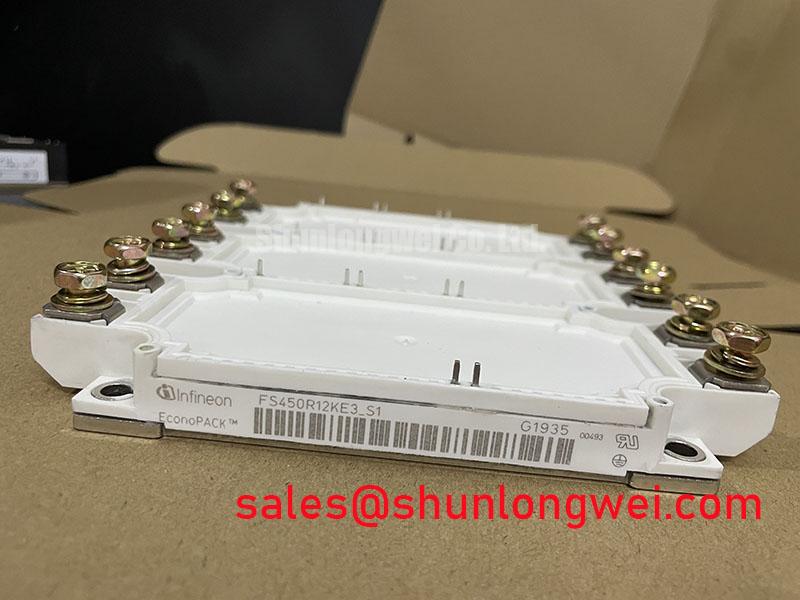
With the traction inverter isolated and its DC link verified discharged, check the removed module for terminal shorts and heat damage before comparing its nameplate with FS450R12KE3_S1. The supplied official ratings identify this Infineon IGBT module as 1200 V and 450 A (Official Specifications). Those ratings establish an initial screening boundary, not approval for a particular high-speed rail or heavy freight locomotive inverter. A replacement assessment still depends on the original equipment documentation, circuit topology, terminal arrangement, cooling interface and protection scheme.
A power-off meter check can find an obvious collector-to-emitter short, but it cannot show whether the opposite switch is being driven on during operation. In an inverter bridge, a rapid collector-voltage change can couple through the gate-to-collector capacitance, often denoted C_res. If the resulting gate disturbance is not controlled, the device that should remain off may conduct while its counterpart is on. That is the practical reason to inspect the gate-drive return path and switching waveforms after a module change, rather than treating a clean static meter reading as proof that the bridge is ready for load.
For FS450R12KE3_S1, the supplied specifications do not establish C_res, gate-charge values, an approved off-state bias or a required clamp circuit. As a Design Consideration, a driver with a low-impedance off-state path or an active Miller clamp can help limit gate rise, but its suitability must be checked against the actual module documentation and driver design. Do not carry a negative gate-bias setting over from another inverter solely because both modules share a voltage class. Capture the off-state gate-to-emitter voltage during the opposite switch’s transition and compare it with the equipment’s approved drive limits.
Trace the gate and emitter connections against the inverter schematic before energizing the bridge. Check connector seating, driver-supply stability and any gate-resistor or clamp components shown on that schematic. Keep the gate-drive path away from high-current switching conductors where the equipment layout permits; the required spacing and routing remain matters for the system design. Infineon’s PrimePACK™ module information provides broader packaging context, but it should not be used to assign a package, pinout or internal feature to this specific part without its matching datasheet.
For a purchasing comparison, FF150R12ME3G is another Infineon part worth evaluating on its own documentation, not a presumed drop-in replacement. Its circuit arrangement, current rating, terminal positions, mounting interface and drive requirements must be checked independently. Matching one prominent rating does not resolve those differences at the inverter cabinet.
Thermal Time Constants (tau_i) and Peak Junction Temperature Margin Calculation
After removing a failed unit, photograph the mounting position and inspect the cooler contact area before cleaning it. Uneven contact marks, displaced interface material or a distorted mounting surface are useful clues when an inverter trips after a heavy acceleration or braking cycle. They do not, by themselves, identify the electrical fault. Record the cooling-system condition and the equipment’s temperature history before attributing a trip to module heating.
The supplied 1200 V and 450 A Official Specifications are not a transient thermal model. Calculating peak junction temperature under a pulsed overload requires the applicable junction-to-case transient thermal impedance, loss data, pulse duration, starting temperature and cooling conditions. A multi-RC model represents the different thermal response times through its tau_i terms; the engineer applies the measured or calculated power-loss history to that model and checks the resulting junction-temperature peak against the module’s documented limit. Without the model coefficients and limit for the exact device, a numerical temperature margin would be speculative.
During a controlled restart, compare case-temperature readings, coolant conditions and phase-current records across comparable operating intervals. A case sensor may respond more slowly than the junction to a short pulse, so a modest case-temperature change does not settle the peak-junction question. Where the inverter records switching events, align those records with the load and temperature traces before changing protection thresholds.
The freewheeling path also deserves attention if abnormal heating coincides with commutation. Diode reverse recovery can contribute to switching loss and voltage ringing; whether its waveform is excessively abrupt depends on the actual diode, circuit parasitics and switching conditions. As a Design Consideration, inspect the existing snubber connections and measure the commutation waveform with suitable equipment before altering a snubber. Such a change needs system-level thermal and emissions validation, not an assumption that the module alone determines radiated EMI. Infineon’s HybridPACK™ Drive information illustrates a distinct module family; it does not establish the construction or qualification of FS450R12KE3_S1.
Overvoltage Trip Prevention via Fast-Switching Ballast Chopper Topology
If a traction inverter trips during deceleration, start with its DC-link voltage record and braking-control command. Regenerated energy may raise the DC-link voltage when the receiving system cannot accept it. A ballast chopper and resistor, where the equipment uses them, provide a controlled dissipation path. The supplied specifications do not confirm that FS450R12KE3_S1 contains a braking switch, or that any particular external chopper is fitted, so identify those functions from the inverter schematic before testing them.
Check the voltage-sensing path, chopper gate command, resistor continuity and accessible connection points under the equipment’s approved service procedure. A chopper command without the expected response may call for investigation of the drive path, switch, resistor or wiring; it is not a diagnosis of the IGBT module on its own. Conversely, a DC-link rise without a command calls for examination of sensing and control conditions. Compare measured switching peaks with the ratings of every affected component, using the actual DC-link operating range and layout parasitics rather than an assumed voltage allowance.
Ballast-resistor selection belongs to the inverter design: the engineer needs the deceleration-energy profile, allowable DC-link range, switching duty and the resistor’s thermal data. The same separation of roles applies upstream. A phase-controlled rectifier, if present in the equipment, can affect DC-link behavior and supply-current harmonics through its firing-angle control; many systems use different front-end arrangements, so confirm the installed topology before investigating firing commands or harmonic mitigation. In the wider power path, FZ600R12KE4 can be reviewed as a separate module in a system-level component comparison, but its name or ratings must not be taken as evidence that it performs rectification or pairs with this device in the target inverter.
Inspect the DC-link protection hardware while the cabinet is safely isolated. Semiconductor fuse coordination cannot be established by comparing current ratings alone: the fuse’s clearing I²t, the prospective fault current and the protected semiconductor’s documented withstand data all matter. If the equipment has suffered a hard short, follow its approved fault-containment and inspection procedure before attempting another powered test.
SCSOA Overcurrent Protection: Implementing Two-Step Gate Voltage Clamping
Before replacing a module after an overcurrent trip, retrieve the driver fault record and inspect the associated phase path for a sustained short. Protection must address faults present when a switch is commanded on as well as faults that arise while it is already conducting. The short-circuit safe operating area, or SCSOA, is device- and condition-dependent. The supplied ratings do not provide an SCSOA boundary, permissible detection delay or prescribed turn-off sequence for FS450R12KE3_S1; none should be inferred from its 450 A current rating.
A staged gate turn-off can be a Design Consideration where abrupt fault-current interruption would create excessive inductive voltage overshoot. Its detection method, gate-voltage levels and timing must come from the exact module data and the approved driver design, then be verified in the assembled inverter. On a service bench, first confirm the driver supplies and fault-signal path using the equipment’s specified checks. Any energized fault-waveform testing requires the facility’s approved safety controls and appropriate instrumentation.
When comparing replacement options, read the terminal drawing alongside the driver schematic. Confirm that the control connections, power terminals, mounting footprint and cooling contact area match the intended assembly before discussing switching behavior. A module that fits physically can still demand a different protection response. For a structured sequence of isolation, measurement and fault-record review, use the Field Engineer’s Handbook alongside the equipment service documentation.
⚠️ Field Alert: Do not reconnect the gate-drive harness until the DC link is verified discharged and the module terminal assignment has been checked against the inverter schematic.