

Content last revised on September 10, 2026
G050VTN01.1 AUO Factory Verified Industrial LCD Display Module
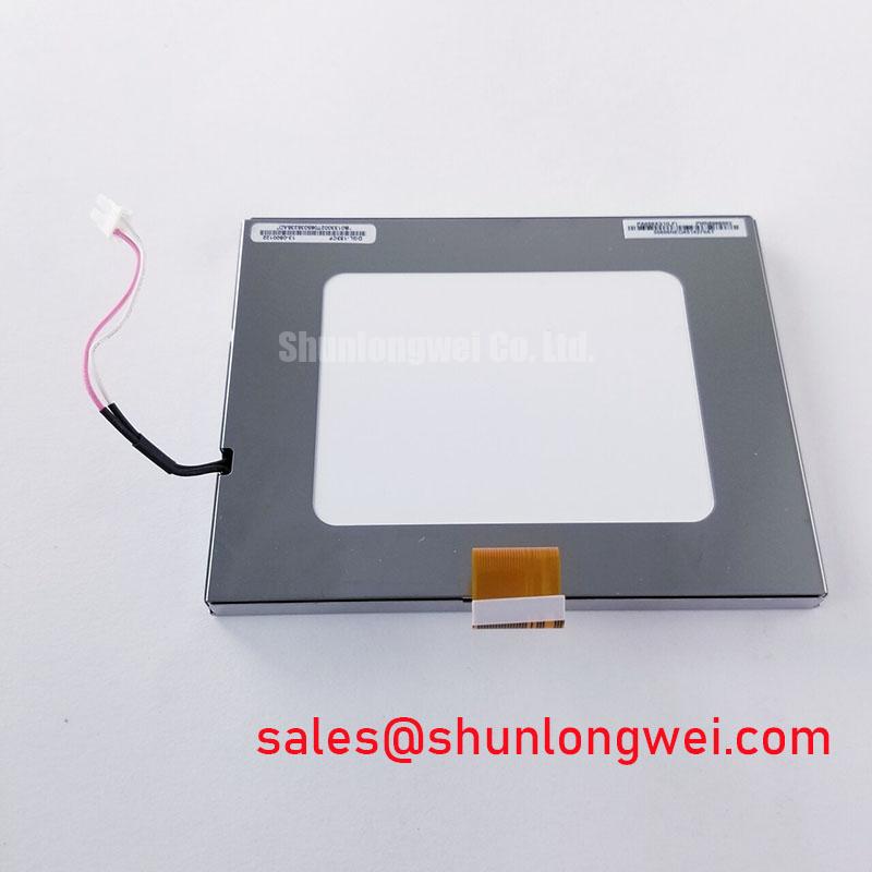
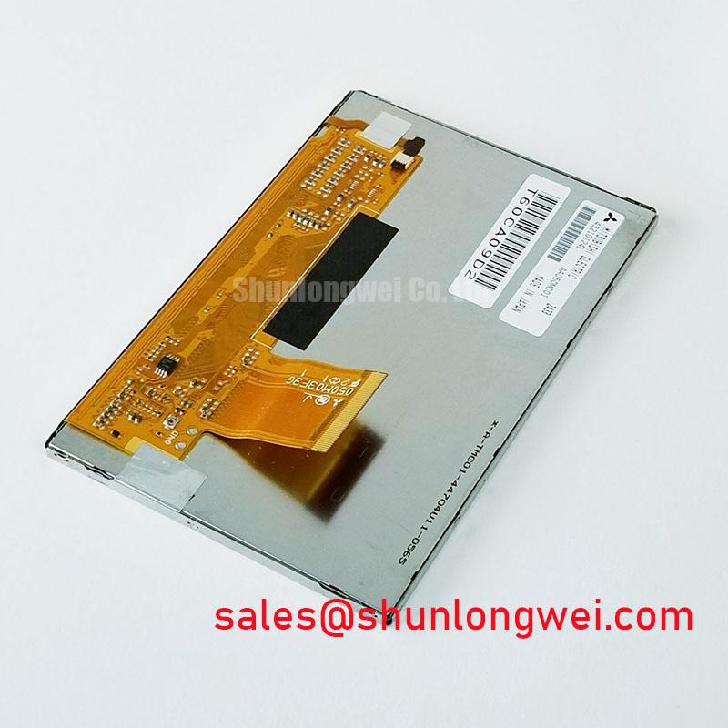
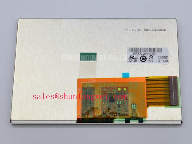
Begin the incoming inspection by comparing the panel marking with G050VTN01.1, checking the TFT LCD module for connector damage, glass-edge impact, frame distortion, and contamination before applying power. Record the observed condition, then compare the original equipment documentation with the replacement panel’s electrical interface, optical format, mounting geometry, and backlight requirements.
The AUO G050VTN01.1 is identified in the available factory information as an Industrial Grade LCD/HMI Panel in a TFT-LCD Display Module package. Its specification status is listed as Official Factory Spec Verified. The supplied product data does not confirm a complete pinout, display resolution, active-area dimension, interface type, logic supply voltage, backlight current, luminance, viewing angle, or operating-temperature rating. Those values should be taken from the original AUO documentation or the equipment manufacturer’s approved panel record rather than inferred from the model number.
| Parameter | Available product information |
| Model | G050VTN01.1 |
| Manufacturer | AUO |
| Product category | Industrial Grade LCD/HMI Panel |
| Package or construction | TFT-LCD Display Module |
| Specification status | Official Factory Spec Verified |
| Interface, timing, dimensions, and backlight data | Verify against the original panel documentation before installation |
High-Humidity Storage Margins and Delamination Prevention Protocols
For a replacement panel held in a warehouse or installed in a process-control enclosure, humidity control begins before the display is connected. Keep the module in its documented shipping protection until the enclosure, workbench, and handling tools are ready. Inspect the polarizer surface, frame perimeter, connector area, and glass boundary under angled light. Look for lifted films, edge discoloration, trapped contamination, or signs that the panel has been exposed to condensation. These observations are handling checks, not evidence of a particular internal failure mechanism.
The requested 60°C and 90% RH condition should be treated as a system-level environmental test point only when it is specified by the equipment qualification plan. No such humidity rating is included in the supplied product parameters for G050VTN01.1. Engineers should verify the AUO environmental specification, storage limits, condensation restrictions, and permitted thermal cycling profile before approving use in a hazardous petrochemical operator station.
Sub-zero operation can increase liquid-crystal response time and alter the visual transition behavior seen during gray-scale changes. That does not establish a guaranteed GTG value for this panel. During qualification, allow the display to reach the intended thermal condition, show neutral gray and moving image patterns, and compare the result with a known-good unit. A slow transition, uneven gray field, or temporary image retention should be recorded against temperature and supply conditions rather than assigned to one cause without measurement.
Perimeter sealing is an enclosure responsibility unless the panel manufacturer’s documentation states otherwise. The system integrator should control moisture ingress through the bezel, cable exit, ventilation path, and service door. Sealants must be checked for chemical compatibility with the display frame, polarizer, adhesive surfaces, and the Zone-2 enclosure design. Applying sealant directly to an unapproved display edge can make later service difficult and may transfer mechanical stress into the glass.
Backlight control also requires confirmation from the original panel record. If the installed system uses PWM dimming, a bench evaluation may examine a control range such as 200 Hz to 1 kHz, but this is a Design Consideration for system tuning and not an official G050VTN01.1 specification. Verify visible flicker, camera banding, audible noise, brightness linearity, and driver compatibility across the complete dimming range. Constant-current behavior, enable polarity, fault reporting, and thermal protection belong to the selected backlight driver and must not be assumed from the LCD model alone.
💡 Pro Tip: Do not power or unplug the panel while the host controller is active; follow the original equipment power-down sequence to reduce connector and interface stress.
Flashlight Dark-Shadow Optical Diagnostic to Isolate Logic and Backlight Faults
A dark-room inspection can help separate an image-generation problem from an illumination problem without relying on an unsupported voltage threshold. First, connect the module only after confirming the connector orientation and the host signal format from the original equipment documentation. Apply a controlled test image containing red, green, blue, white, black, and neutral-gray fields. Observe whether the image changes consistently when the backlight is enabled and whether the displayed pattern follows the expected signal sequence.
Second, place a flashlight at approximately a 45-degree angle to the front surface and inspect the dark region while the display is commanded to show a visible image. If image content can be seen in the shadowed area, the logic path may be producing an image while the illumination path requires further examination. If no image content is visible, verify the host output, panel enable signals, timing relationship, connector seating, and supply behavior with the approved test method. This procedure narrows the diagnostic path; it does not prove a specific component failure.
Third, run the primary-color sequence again while observing the entire active area for fixed lines, split fields, intermittent columns, or localized defects. A line defect that remains in the same physical position across multiple input images may require inspection of the panel interface, bonding region, cable seating, and controller signal quality. Avoid pressing the glass or flex connection during this test. Mechanical pressure can change the symptom and create an unreliable diagnosis.
The available factory information does not provide a backlight lifetime rating or a brightness-retention curve for this product record. A statement such as “50,000 hours to 50% brightness” must not be assigned to G050VTN01.1 without the applicable AUO datasheet or an authoritative qualification document. For an industrial HMI, the meaningful test record should include ambient temperature, enclosure temperature, drive current, dimming method, duty pattern, ventilation condition, and measured luminance over time.
When evaluating a field replacement, compare the known-good unit and the suspect unit using the same controller, cable, image pattern, backlight command, and measurement location. Check whether the symptom follows the panel or remains with the host assembly. This substitution test is an Engineering Recommendation for fault isolation, not a manufacturer-defined acceptance limit. Any Zone-2 certification requirement applies to the complete operator station and enclosure assembly; the LCD module alone should not be represented as independently certified for the hazardous location.
Radiated Emissions Evaluation and Backplate Grounding
Before installing the display near a variable-frequency motor drive, inspect the routing between the controller, display connector, backplate, and enclosure entry point. Keep high-current switching conductors physically separate from the display cable, avoid unnecessary cable loops, and preserve the shielding method defined by the equipment design. The G050VTN01.1 product information supplied here does not identify the interface as LVDS or TTL, so the actual cable and transmitter arrangement must be confirmed from the original panel documentation.
A 360-degree shield termination, star-ground arrangement, or common-mode ferrite may be considered during system EMC development, but none is an official panel specification. The correct bonding method depends on enclosure construction, cable shield current, protective-earth architecture, connector design, and the frequency range producing the disturbance. Engineers should measure the complete assembly while the nearby drive operates through the relevant switching states.
Pixel jitter, horizontal noise bands, intermittent color changes, or display resets can have several possible contributors, including signal integrity, power disturbance, ground reference movement, connector contact quality, or electromagnetic coupling. Use an oscilloscope and a controlled cable arrangement to compare the display clock and data path with a known-good configuration. Do not label a particular symptom as proof of a cable, panel, or controller failure without that comparison.
If the verified interface is a differential display link, the system designer may evaluate a characteristic impedance target such as 100 Ω ±10% where required by the transmitter and receiver documentation. This is a Design Consideration for the complete interconnect, not a confirmed G050VTN01.1 factory parameter. Pair matching, return-path continuity, connector transitions, and cable construction must be reviewed together. A skew objective such as 50 ps may also appear in a host design specification, but it should be accepted only when supported by the actual interface datasheet and measured timing budget.
EMC compliance belongs to the finished operator station. The display module does not independently establish CISPR Class A or Class B compliance. For a petrochemical monitoring terminal, the integrator should test radiated and conducted behavior with the final enclosure, power supply, controller, cable shield termination, touchscreen or protective window if present, and all external wiring installed. The relevant compliance declaration and hazardous-area assessment must come from the complete equipment manufacturer.
For background on display construction, interface selection, and general industrial TFT integration, engineers can consult The Ultimate Guide to Industrial TFT LCD Technology. It should be used as general engineering reference material, while the original AUO panel documentation remains the authority for model-specific limits.
VESA and JEIDA Data Mapping with Even and Odd Channel Signal Integrity
Confirm the panel interface before the first live connection. The model record supplied for G050VTN01.1 does not publish a logic supply voltage, connector pin assignment, data mapping, pixel clock range, power-on timing, or data hold requirement. The system integrator should verify the required supply voltage from the original panel documentation. Do not select between possible voltage options or assume a mapping standard from connector appearance alone.
When the host uses an LVDS link, the engineer should verify whether the transmitter expects JEIDA or VESA bit mapping and whether the panel uses the same ordering. A mapping mismatch can produce incorrect colors, exchanged bit significance, or structured image artifacts even when the cable is mechanically compatible. Check the red, green, and blue bit positions, synchronization fields, odd and even channel assignment, clock polarity, and unused signal treatment against the approved pinout.
Even and odd channel verification is best performed with a fixed color-bar pattern followed by alternating pixel and gray-scale patterns. Capture the transmitter output and compare the observed channel activity with the panel timing documentation. If the image is divided vertically, shows repeated color groups, or changes when the cable is moved, inspect channel continuity, connector retention, ground reference, and transmitter configuration before concluding that the LCD glass is defective.
A host design may define a differential impedance near 100 Ω and a controlled power-on rise-time window such as 0.5 ms to 10 ms. These values are Engineering Recommendations or system requirements only when they appear in the applicable transmitter, receiver, or equipment specification. They are not confirmed factory limits for G050VTN01.1. The final design should verify inrush behavior, reset release, panel enable sequencing, clock stability, and signal validity across the intended temperature range.
Clock jitter and data hold margin should be checked at the panel connector rather than only at the controller output. Cable length, connector discontinuities, ground bounce, supply ripple, and enclosure coupling can reduce the usable timing margin. Use the original timing specification to define pass and fail criteria, then repeat the measurement during cold start, warm operation, brightness changes, and nearby drive activity. A clean static image at room temperature is not sufficient evidence of full industrial compatibility.
For a same-size or same-resolution comparison during sourcing review, engineers may examine KCG047QV1AA-G210 as a separate product record. It should not be treated as a drop-in substitute until dimensions, active area, connector position, interface protocol, timing, mounting points, backlight behavior, and enclosure approval have been checked against the equipment design.
In a hazardous petrochemical operator station, the display replacement must also be evaluated within the certified mechanical and electrical assembly. Confirm the viewing-window opening, gasket compression, thermal path, cable bend allowance, grounding arrangement, and service procedure with the enclosure designer. The G050VTN01.1 product category identifies an industrial TFT-LCD display module; it does not, by itself, define the certification status of the finished Zone-2 equipment.