

Content last revised on October 26, 2026
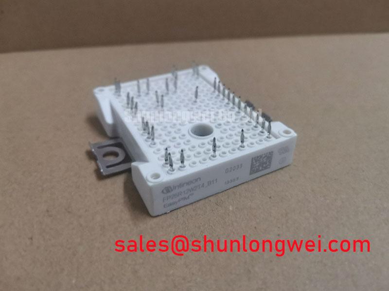
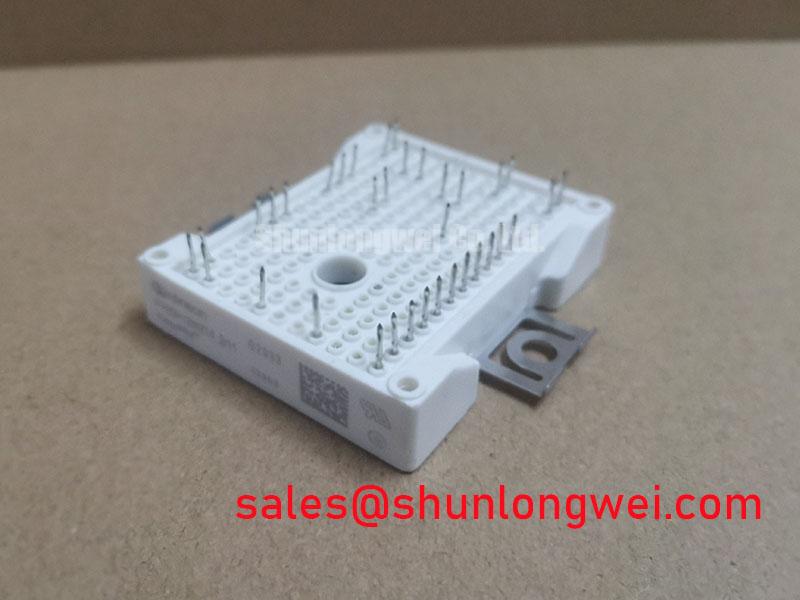
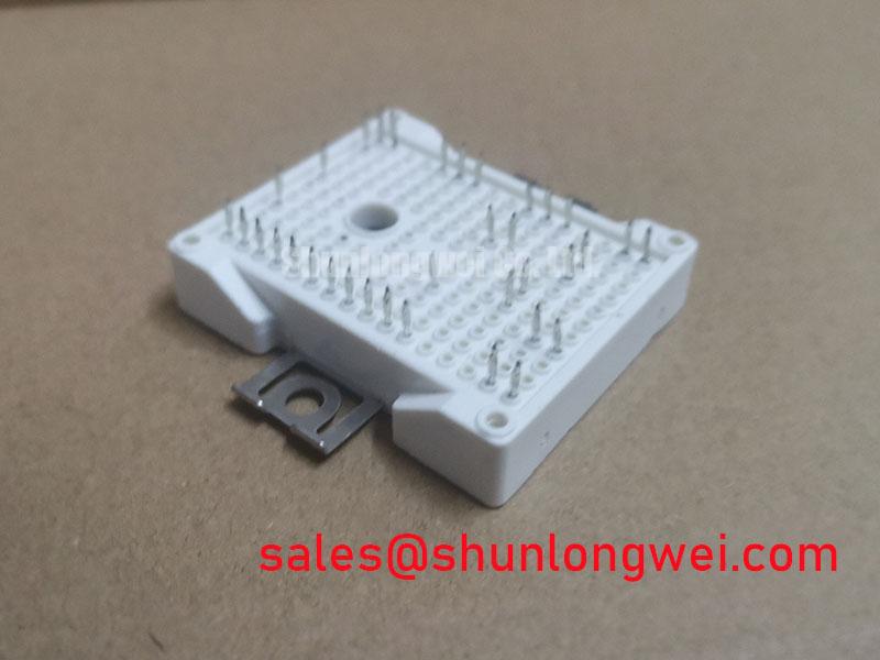
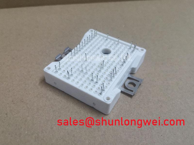
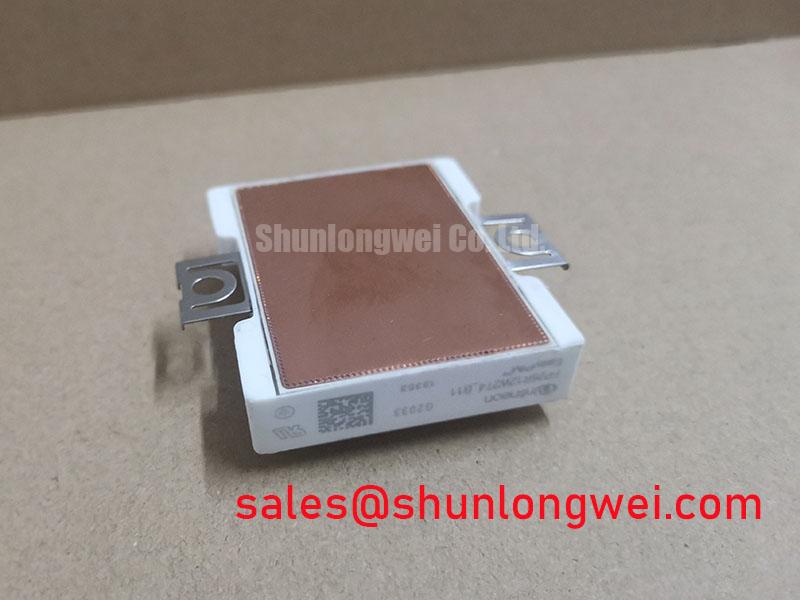
FP26R12W2T4_B11 Circuit Protection & Reliability: Thermal Grease Pump-Out
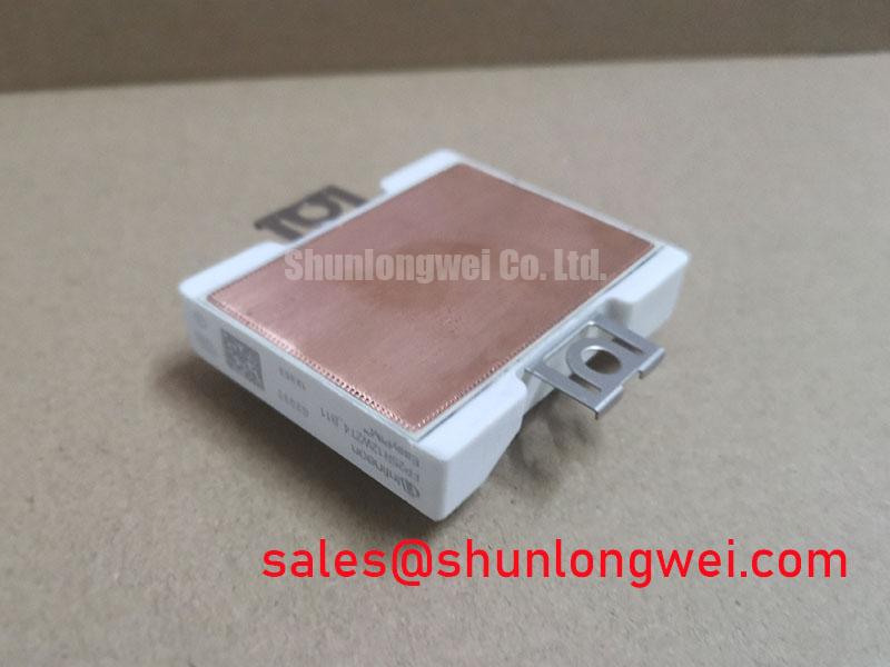
Inspect the heatsink contact area for raised burrs, trapped debris, previous interface residue, and uneven mounting surfaces before positioning the module. As a Design Consideration, evaluate contact geometry using the applicable package drawing rather than assuming a copper baseplate, prescribed convexity, or a universal flatness tolerance. The relevant question is whether the specified mounting arrangement can produce stable thermal contact without imposing excessive mechanical stress on the package or circuit board.
Thermal grease pump-out describes displacement of interface material during repeated thermomechanical movement. Grease visible around a mounting footprint does not, by itself, establish unacceptable thermal resistance. During a permitted service inspection, compare the contact imprint, remaining coverage, heatsink condition, and mounting hardware position. Localized dry areas can justify further investigation, but interface condition should be assessed alongside temperature measurements and the assembly history rather than treated as a single-cause diagnosis.
As an Engineering Recommendation, use the interface material and application method specified for the equipment and module assembly. Control coverage with a repeatable dispensing or printing process rather than judging the joint by the amount squeezed out at the edges. A thinner layer is not automatically better when surfaces are uneven, and extra compound cannot correct a distorted heatsink. Neither a generic interface thickness nor a familiar fastener torque should become an acceptance limit for this particular package.
Where the approved mounting instructions specify multiple fasteners, progressive cross-pattern tightening can help distribute loading. The actual sequence, torque, washers, and fixture support must follow those instructions. Keep the circuit board supported during assembly, and check that connector engagement or terminal attachment does not pull the module away from its intended seating position. These are assembly controls, not additional FP26R12W2T4_B11 electrical specifications.
After reassembly, compare temperature behavior under a repeatable operating condition using the equipment’s approved measurement points. Separate poor contact from restricted airflow, changed loading, and abnormal switching loss before replacing the thermal interface again. If temperature changes follow a mechanical intervention, preserve the installation records and contact photographs; they provide a more useful diagnostic trail than an unsupported claim about expected service life.
Transient Dynamics & Electrical Design: Separating Driver Return from Main Current on FP26R12W2T4_B11
Trace the gate-driver return from its output stage to the emitter connection identified in the exact module terminal drawing. A dedicated auxiliary emitter connection must not be inferred from the EasyPIM package name. Where the documented terminal arrangement provides a separate driver return, keep that path distinct from the main load-current route; otherwise, assess the shared connection explicitly in the driver-loop layout.
As a Design Consideration, shared emitter-path inductance can shift the driver’s local reference during rapid current changes. This can alter the effective gate-to-emitter waveform even when the controller command remains clean. Inspect the gate and return routing together, including connectors and board transitions, and measure at the relevant module terminals with an appropriate differential probing arrangement. A long probe loop can introduce ringing that resembles a circuit defect.
Negative turn-off bias is a driver-design option, not an automatic requirement established by the module’s voltage rating. When the equipment uses it, evaluate the complete gate waveform, including negative excursions, against the applicable gate limits. Check local driver decoupling, return continuity, and any gate-clamping components before attributing unwanted pulses solely to insufficient bias. Changes to gate resistance or bias should be assessed for their effect on both switching stress and driver behavior.
Complementary switching commands also require timing verification at the power stage. As an Engineering Recommendation, establish dead time from propagation-delay variation, actual device turn-off behavior, and the operating temperature range, then verify the resulting non-overlap under representative conditions. Hardware interlocking should prevent conflicting commands, while the validation should include enable transitions and fault recovery rather than only steady operation.
For procurement comparisons, retain the exact suffix and compare the terminal drawing, circuit configuration, mounting geometry, and driver requirements before considering another module. The FP100R12KT4-B11 is a separate comparison candidate, not an established drop-in replacement. The table distinguishes the supplied FP26R12W2T4_B11 specifications from items requiring a model-specific comparison.
| Comparison item | FP26R12W2T4_B11 | FP100R12KT4-B11 |
|---|---|---|
| Manufacturer | Infineon | Infineon |
| Voltage rating | 1200 V — Official Specification | Consult model datasheet |
| Current rating | 26 A — rated collector current under the specified datasheet conditions | Consult model datasheet |
| Package | EasyPIM — Official Specification | Consult package drawing |
| Replacement assessment | Match the original equipment configuration | Compare topology, terminals, mounting, and switching requirements |
When assessing compatibility with a compact industrial inverter or high-speed CNC spindle drive, designers should check the complete power-stage schematic rather than compare current ratings alone. If the review also includes a separate rectification or complementary power stage, the BSM75GP120 can be examined in that circuit context; its inclusion does not establish that either device requires the other.
Benchtop Waveform Tuning: Galvanic Gate Drive Isolation for FP26R12W2T4_B11 Applications
Identify the gate driver’s isolation barrier and its documented insulation classification before interpreting switching waveforms across different reference potentials. Reinforced insulation is a property of a specified isolation arrangement and its implementation; it is not established by the FP26R12W2T4_B11’s 1200 V rating. Likewise, module blocking voltage, isolation withstand voltage, and permissible continuous working voltage describe different electrical boundaries.
As a Design Consideration, compare the driver’s common-mode transient immunity with the switching conditions measured in the equipment. Inspect isolation-side supply stability and receiver behavior while observing the gate waveform. Common-mode disturbance can enter through supply capacitance, layout coupling, or measurement equipment, so an unexpected pulse should be correlated with its timing and reference path before assigning a cause. The Infineon IGBT Modules & Discretes Official Portfolio provides manufacturer context for the device family, rather than a system-level isolation approval.
Where the equipment schematic includes a bootstrap supply, examine the supply voltage throughout the switching sequence rather than only at idle. Capacitor charge availability depends on gate-drive demand, leakage, and the available recharge interval. The bootstrap diode’s recovery behavior and charging path can also affect local disturbances. Component selection and acceptance limits belong to the documented driver circuit; a module rating alone does not determine capacitor size or diode suitability.
For static checks, compare corresponding diode paths under consistent conditions without assigning a universal forward-voltage pass band. Manufacturer material on Infineon IGBT Discretes & Co-Pack Diodes helps explain IGBT and diode behavior, but discrete-device information should not be substituted for this module’s terminal map or test limits.
Use an approved, current-limited commissioning procedure to correlate driver supply voltage, command timing, and gate-to-emitter response before increasing operating stress. For broader troubleshooting context, IGBT Design & Integration connects gate-drive, thermal, and topology considerations. Close the specific investigation by repeating the measurement with unchanged probe placement and operating conditions, confirming whether the observed disturbance changed with the circuit correction rather than with the measurement setup.