Content last revised on September 10, 2026
Suppressing Localized Thermal Gradients to Prevent Chronic Optical Yellowing (Color Shift)
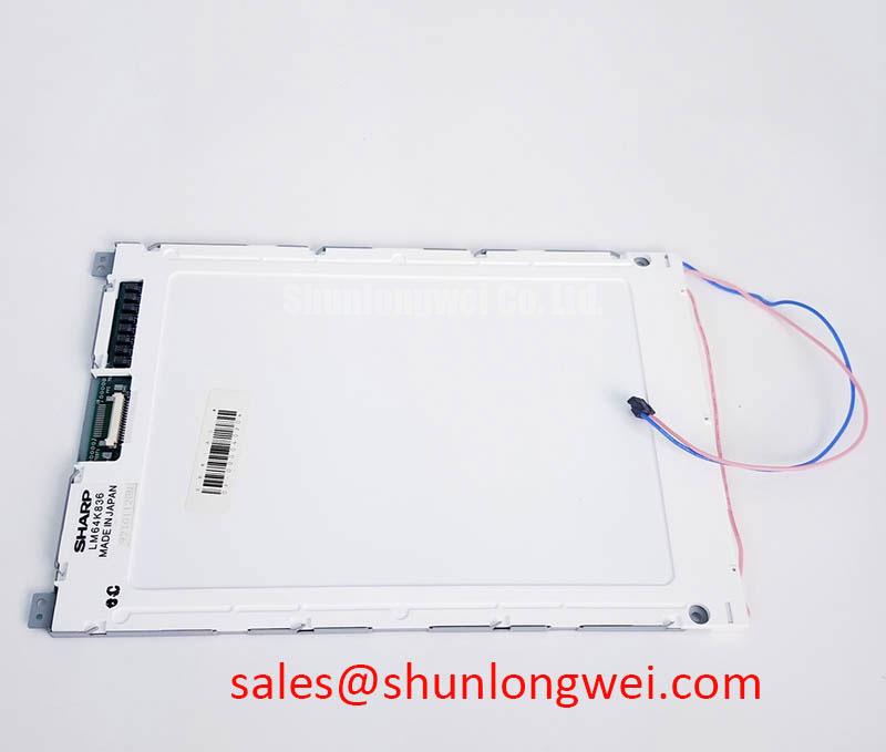
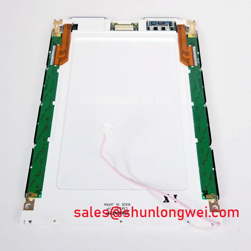
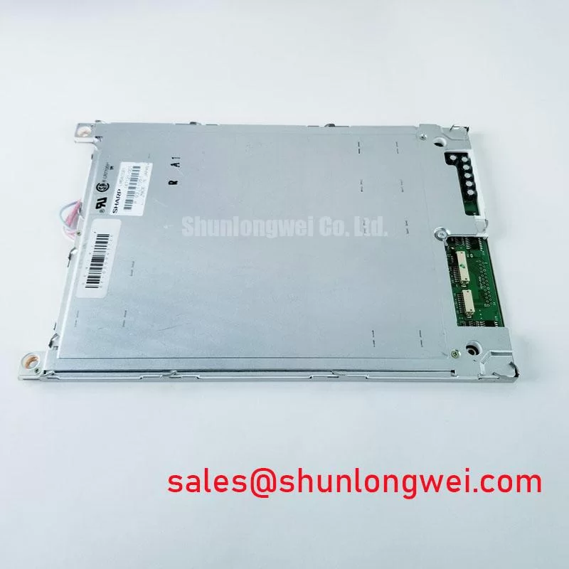
Begin an LM64P838 service inspection with the panel disconnected from the host controller, then examine the TFT-LCD display module perimeter, mounting points, connector area, and visible glass surface for mechanical stress, contamination, or evidence of uneven enclosure compression. The LM64P838 is identified as a Sharp industrial grade LCD/HMI panel in a TFT-LCD display module format. Its verified factory classification should be used as the starting point for replacement evaluation, while the original machine documentation remains necessary to confirm electrical interface, timing, backlight arrangement, mechanical dimensions, and controller compatibility.
For equipment repair work, the module part number alone is not enough to approve installation. Record the original panel label, compare the host cable orientation, inspect the mating connector condition, and preserve any gasket, bezel, shielding, or mounting hardware removed during disassembly. These details often determine whether a replacement display will sit evenly in a CNC operator panel or robot teach pendant enclosure.
| Parameter | Verified Product Information |
|---|---|
| Model | LM64P838 |
| Manufacturer | Sharp |
| Product Category | Industrial Grade LCD/HMI Panel |
| Module Format | TFT-LCD Display Module |
| Specification Status | Limited Product Information Verified |
The available verified product information does not establish a specific signal standard, supply voltage, viewing technology, brightness rating, temperature range, contrast ratio, backlight type, or operating-life rating. The system integrator should verify those requirements from the original panel documentation and the host equipment design before applying power.
Thermal Gradient Inspection and Viewing Direction Alignment
During planned maintenance, inspect the panel cavity rather than treating the display module as an isolated assembly. Dust accumulation near ventilation paths, a distorted rear support plate, or a gasket that no longer rests evenly can change how heat is retained around the display. A warmer zone near one edge can contribute to uneven optical appearance over time, but any observed color shift should be investigated as a system-level condition rather than attributed to one internal material or one failure mechanism.
For an LM64P838 installation, the enclosure should support the module across the intended mounting surfaces without concentrating force at a corner or along a narrow edge. The display should not be used to compensate for an uneven bezel, damaged support frame, or warped front panel. Where a machine cabinet uses heat-spreading rails, their contact arrangement, insulation method, and clearance must be assessed against the original mechanical design. This is a Design Consideration, not an official mounting specification for the LM64P838.
In industrial operator stations, localized heating can also come from adjacent power supplies, processor boards, motion-control hardware, or restricted airflow. Maintenance personnel can compare the panel cavity with a known-good assembly, checking whether the rear enclosure is clean, whether the mounting frame is flat, and whether the display sits without visible torsion. This approach provides useful evidence without assuming that a visible optical change has one definite cause.
⚠️ Maintenance Note: Inspect cooling paths and perimeter gasket contact during scheduled service because blocked airflow or uneven compression can increase thermal and mechanical stress on the display assembly.
Signal routing also deserves inspection when the host board has been repaired or modified. The LM64P838 factory classification does not confirm a differential interface, differential impedance requirement, or skew limit. If the original equipment uses controlled-impedance data pairs, maintain the established routing practice and compare waveforms with a known-good signal path before deciding that a display module is responsible for intermittent image behavior. Cable damage, connector oxidation, grounding changes, and controller-board faults can produce similar symptoms.
Viewing-Angle Behavior and Grayscale Appearance
Viewing-angle behavior must be verified from the original panel documentation or from comparison with the removed working display. The verified information for LM64P838 identifies a TFT-LCD display module but does not confirm normally white TN operation, IPS construction, MVA construction, a symmetrical viewing cone, or a specified anti-glare surface treatment. These characteristics should not be assumed during a field replacement decision.
For a CNC operator panel, assess the actual viewing position of the machine operator. A display that appears acceptable directly in front of the enclosure can show grayscale changes when observed from above, below, or from an oblique angle. Before final assembly, power the system through its intended host electronics and inspect alarm pages, low-contrast graphics, menu backgrounds, and large neutral-color areas from the normal operating position. If the machine uses a protective window or touch overlay, inspect that assembly separately for haze, scratches, adhesive aging, or trapped moisture that can alter perceived contrast.
Ambient lighting is equally important. Strong overhead illumination, direct work lights, and reflections from nearby metal surfaces can make an otherwise functional panel difficult to read. Surface glare can originate from the front glass, external overlay, protective window, or enclosure angle. Altering the display surface with unapproved films, coatings, or cleaning chemicals can introduce new optical problems, so the maintenance team should follow the equipment maker’s approved cleaning and protection practice.
Cold-start image response should also be evaluated in the real installation environment. Liquid-crystal behavior can change with temperature, yet the official information supplied for this model does not define a low-temperature operating range or authorize a heater-strip strategy. Where the host machine includes cabinet heating or condensation control, verify that its control method remains functional and that warm air is not directed unevenly across the display rear surface. The objective is stable enclosure conditions, confirmed by the machine-level design and validation process.
Digital RGB Bus Synchronization and Logic Power Rail Verification
Do not assume a TTL 24-bit RGB bus, a logic supply value, a power-on timing window, or a JEIDA or VESA mapping for the LM64P838 without the original interface documentation. These details are not established by the verified factory information provided here. A panel can physically connect to a host harness while still being electrically unsuitable if the signal assignment, logic levels, enable sequence, or display timing differs.
Before replacement, document the original connector keying, cable position, host-board connector marking, and any intermediate interface board. With the equipment safely isolated, examine the cable for crushed sections, loose strain relief, or contamination at the contact area. After installation, verify that the host controller completes its normal initialization sequence and compare the image with a known-good machine where possible. Split images, unstable lines, incorrect colors, frozen areas, or an all-white display may indicate a problem in the signal path, interface configuration, cable, supply rail, or controller sequence; they should not be treated as proof of a panel defect without measurement.
Power sequencing is particularly relevant when a repaired operator terminal has multiple rails or separate control boards. The system integrator should verify the required supply voltage from the original panel documentation and confirm that the host controller applies and removes power according to its specified sequence. This is an Engineering Recommendation for system integration, not a published electrical specification for the LM64P838. Oscilloscope checks against a known-good signal path can help isolate whether image artifacts occur before the panel receives valid data.
Where an auxiliary display assembly or related screen solution is being evaluated, LMS700KF01-001 can be reviewed as a separate product reference. Its use does not establish electrical or mechanical compatibility with LM64P838. Any comparison should include connector definition, host electronics, power architecture, enclosure fit, and the complete display stack.
Long-term static screens deserve attention in industrial HMI service. Alarm dashboards, status pages, machine recipes, and teach-pendant control layouts can remain on screen for extended periods. If persistent image retention, contrast change, or uneven appearance is reported, inspect the host operating pattern, brightness control behavior, environmental exposure, and front-surface condition before drawing conclusions. The supplied official information does not define static-image endurance or backlight decay characteristics for this model.
Optical Luminance Degradation and Backlight Retrofit Considerations
A dim or uneven display should be diagnosed at the assembly level. Verify the host output, display cable, control signals, protective window condition, and enclosure ventilation before specifying a modernization path. The available official information identifies LM64P838 as a TFT-LCD display module, but it does not confirm whether the installed unit uses a particular backlight technology, ignition requirement, dimming method, luminance value, or lifetime curve. It is therefore inappropriate to assign CCFL or LED characteristics to this specific model without the original Sharp documentation.
If a repair program considers converting an older display arrangement to a newer lighting architecture, treat that work as a redesign rather than a direct display substitution. The replacement assembly must be assessed for mechanical fit, optical alignment, power-source capability, dimming control, thermal behavior, safety clearances, and controller compatibility. A retrofit that changes the panel stack, light source, or interface can affect screen uniformity and serviceability even when the visible area appears similar.
Optical bonding can improve resistance to dust ingress between external layers when it is specified and implemented as part of a compatible display assembly. It should not be added casually to an existing LM64P838 installation without confirming stack thickness, touch function, bezel clearances, and rework implications. The same restraint applies to anti-glare films and sealing compounds. Their performance depends on the complete mechanical stack and the environmental demands of the host equipment.
For replacement comparison, LM64P10 can be reviewed as a related display option during engineering evaluation. Compatibility must be established from verified documentation and the original equipment interface; a related model name or similar class does not by itself confirm a direct replacement relationship.
When recurring display faults are being investigated across several machines, record the installed location, cabinet condition, front-window state, operating pattern, cable condition, and observed visual symptom before changing parts. This disciplined record helps separate panel-level observations from enclosure, controller, power, and operator-interface conditions. For broader maintenance methods covering industrial screen assemblies, see Industrial Display & HMI Solutions.