
Content last revised on October 30, 2026
FZ200R65KF2 Circuit Protection & Reliability: Separating Driver Return from Main Current
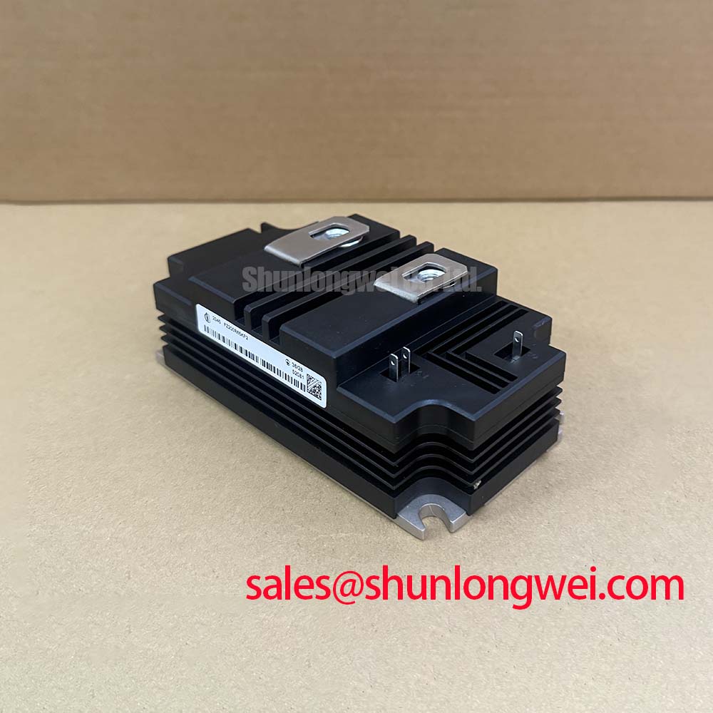
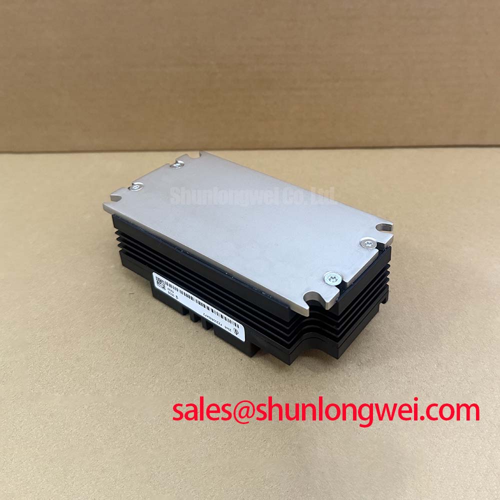
I trace the gate-driver return to the module terminal drawing before reconnecting a repaired power stage, distinguishing the main emitter current path from any designated auxiliary emitter connection. For the Infineon FZ200R65KF2, terminal identification must follow the matching package drawing rather than the position or appearance of a small connection. A driver return routed through a load-current conductor can pick up switching-induced voltage, so a waveform referenced to the controller ground may conceal the actual gate-emitter stress.
Design Consideration: inspect the complete outgoing gate path and its return together. Their routing should minimize enclosed loop area and avoid sharing impedance with the main commutation path. Where the terminal drawing provides a dedicated auxiliary emitter return, the driver reference belongs on that designated connection. During powered evaluation, measure gate-emitter voltage locally with appropriately rated differential instrumentation; compare the local waveform with the driver output to distinguish device-terminal behavior from interconnect effects.
Miller-induced gate movement needs a separate check from ground bounce. Collector-emitter voltage transitions couple current into the gate circuit, while shared emitter inductance changes its reference potential. Designers should assess driver sink capability, off-state control, and any clamp function against the measured disturbance. External gate resistance affects damping and switching speed, but increasing resistance indiscriminately can increase switching losses or weaken control during a disturbance.
The 6500 V collector-emitter rating and 200 A continuous collector current at case temperature 80°C are Official Specifications, not simultaneous operating guarantees under every switching condition. The permitted operating envelope also depends on junction temperature, pulse conditions, cooling, and the safe operating area. Derating should therefore follow the actual electrical and thermal duty rather than a fixed percentage chosen from the headline ratings.
Design Consideration: coordinate desaturation detection with the normal turn-on transient, then assess the fault response against the applicable short-circuit safe operating area. Desaturation sensing is a protection function, not a direct junction-temperature measurement. A controlled soft shutdown can reduce fault-current interruption stress, but its timing must balance switching overvoltage against fault energy. No short-circuit duration or protection threshold follows from the voltage and current ratings alone.
Engineering Recommendation: keep commutation busbar paths compact and geometrically balanced to reduce turn-off overshoot, then establish the remaining voltage margin through system-representative double-pulse measurements. For parallel branches, the Infineon IGBT paralleling application note provides relevant guidance on electrical symmetry. A positive temperature coefficient, where established by the device characteristic curves at the operating point, does not by itself ensure dynamic current sharing.
Assembly Integrity & Layout Architecture: Managing Baseplate Curvature and Mounting for FZ200R65KF2
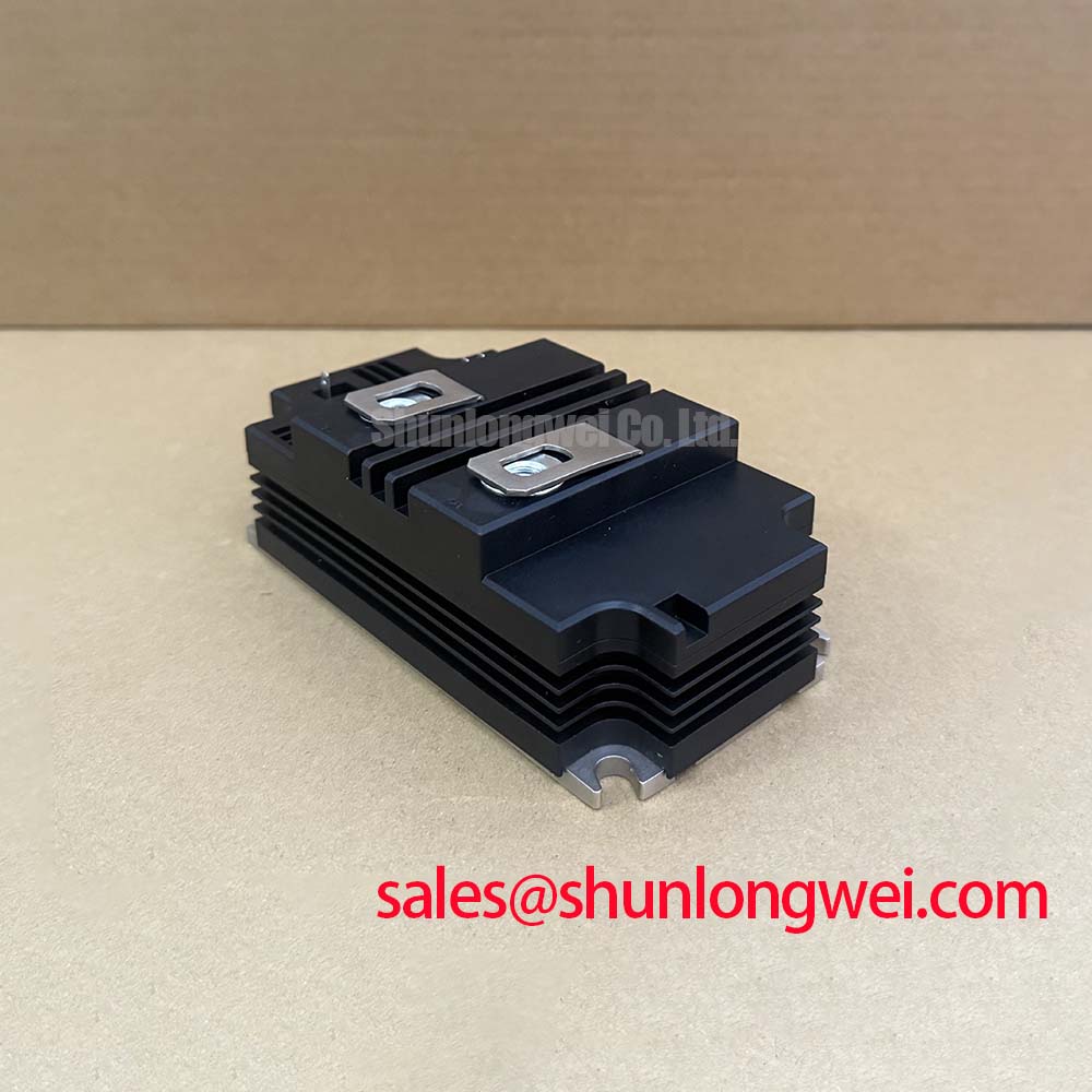
Check heatsink flatness, mounting-surface cleanliness, and the module’s seating before tightening the mounting hardware. The AlSiC baseplate is an Official Specification for the FZ200R65KF2; it does not remove the need to control the external thermal interface. Burrs, trapped debris, uneven compound distribution, and mechanical distortion can interrupt heat transfer even when the cooling circuit itself is functioning correctly.
Design Consideration: assess baseplate curvature against the manufacturer’s mounting instructions rather than trying to flatten the module with screw force. The interface material must accommodate the intended mating geometry without creating excessive thermal resistance. Apply it using a controlled process appropriate to its viscosity and the surface condition. Inspect trial assemblies for coverage and displaced material; a visually thick perimeter bead does not establish that the active contact region is free of voids.
Use the specified mounting sequence and torque for the actual module and fastener arrangement. Progressive tightening helps control seating, but neither a universal screw torque nor a universal interface thickness should be assigned to this part. Keep busbar alignment independent of the mounting operation so that electrical connections do not pull the housing into position. Recheck seating after assembly changes that alter cable forces, supports, or cooling hardware.
The relationship between thermal interfaces and operating temperature is discussed in The Advanced Thermal Management Revolution. This supporting technical article provides context for evaluating the heat-removal path; it is not an FZ200R65KF2 mounting specification. For this module, the practical task is to establish repeatable contact between its baseplate and the selected heatsink under the approved assembly conditions.
Gate-driver selection belongs in the same integration review because connector placement and mounting geometry influence the drive loop. Design Consideration: assess source and sink capability using gate-charge behavior, desired transition time, driver output impedance, and the complete gate circuit. Choose external damping through waveform evaluation, considering turn-on and turn-off separately where the circuit supports that arrangement. Observe gate ringing, collector overshoot, switching loss, and driver heating together rather than optimizing only the cleanest-looking gate trace.
For procurement comparisons, FZ600R65KF2 is a separate candidate for engineering review, not an established direct replacement. Compare its terminal geometry, mounting outline, gate requirements, switching characteristics, and thermal interface before considering a substitution. Infineon’s EasyPACK product information illustrates a distinct module platform; its packaging and qualification details must not be transferred to the FZ200R65KF2.
Benchtop Waveform Tuning: Gate-Emitter Fault Screening and Stress Evaluation on FZ200R65KF2
Disconnect the module from parallel electrical paths and verify that stored energy has been discharged before using a multimeter’s diode-check function. With the gate held at the emitter reference using an appropriate handling arrangement, compare main-terminal readings in both polarities against the module circuit diagram. The objective is to identify inconsistent conduction behavior, not to assign a universal forward-voltage acceptance window to a high-power semiconductor.
Design Consideration: account for the antiparallel diode path shown in the device circuit when interpreting collector-emitter measurements. Meter test current, temperature, terminal contact, and connected circuitry can change the displayed result. A repeatable reading that differs substantially from a comparable known-good module warrants further investigation, but does not independently identify the failed internal element. Repeat questionable measurements after checking probe contact and removing external snubbers or sensing networks from the measurement path.
Gate screening requires particular restraint. A multimeter can reveal a gross conductive fault, but it cannot demonstrate gate-oxide integrity across the operating envelope or quantify leakage at a specified bias unless the instrument and test method support that measurement. Use controlled gate-leakage testing only within the manufacturer’s permitted terminal conditions, with suitable current limiting and electrostatic-discharge precautions. Avoid applying an insulation tester across the gate-emitter terminals.
After static screening, a controlled switching evaluation can separate driver behavior from power-path effects. Design Consideration: validate instrument common-mode capability, probe placement, and measurement bandwidth before interpreting narrow spikes. Capture gate-emitter voltage, collector-emitter voltage, and current with a consistent timing reference. A change in probe-loop geometry that changes the apparent ringing is a reason to examine the measurement arrangement before modifying the gate circuit.
During tuning, investigate overshoot and gate disturbance as related but distinct observations. Collector overvoltage may involve commutation inductance and current fall rate; gate oscillation may involve driver impedance, capacitive coupling, or reference-path movement. Changes should be evaluated individually so their effects remain attributable. The specified IGBT3 / Fieldstop technology identifies the device technology, but does not supply a system-specific switching frequency, gate resistor, or fault-response setting.
When assessing compatibility with a utility-scale 1500 V high-power central solar photovoltaic inverter, engineers should compare topology, switching duty, losses, and cooling requirements rather than treating the module’s blocking rating as proof of suitability. In the surrounding power architecture, FZ750R65KE3 can be evaluated as a separate power-module candidate where the circuit requires it; its name alone does not establish a rectifier role, complementary pairing, or interchangeability.
Preventing Spurious Faults: Pollution Degree 3 Creepage Distance Guidelines for FZ200R65KF2
Inspect the external insulation paths between power terminals, mounting structures, and the baseplate for deposits, moisture tracks, and damaged surfaces before planning an insulation test. Dust accumulation can change the condition of an otherwise clean assembly, so record the environment and surface condition alongside the electrical result. Cleaning should follow material-compatible procedures and leave the assembly dry before evaluation.
The 10.2 kV RMS insulation test voltage at 50 Hz for 1 minute is an Official Specification. It is a defined test condition, not a continuous working-voltage rating or evidence that the installed equipment meets a particular railway or industrial safety standard. It also does not establish a field acceptance threshold for insulation resistance measured with a DC instrument.
Design Consideration: an insulation-resistance test needs an approved service procedure identifying terminal grouping, isolated accessories, test voltage, duration, discharge method, and acceptance criteria. Separate sensitive gate-drive electronics and connected monitoring circuits as that procedure requires. Evaluate the module-to-baseplate insulation path without interpreting a single resistance measurement as proof of the integrity of a particular internal ceramic structure.
Pollution Degree 3 creepage assessment is an equipment-level insulation-coordination task. Under the applicable edition of IEC 60664-1 and the relevant equipment standard, the designer determines distances using working voltage, insulating-material classification, pollution conditions, and the insulation function. Clearance assessment also involves the relevant impulse conditions and installation environment. Neither distance should be selected from the module’s collector-emitter rating alone.
Keep external barriers, terminal covers, and wiring supports positioned so that assembly tolerances do not shorten the intended insulation paths. If leakage-related faults recur, compare results before and after controlled cleaning and drying, inspect adjacent busbars and supports, and document whether the behavior follows the module or its installation. Resume operation only after the service acceptance checks are satisfied and the source of the abnormal insulation behavior has been addressed.