Content last revised on February 10, 2026
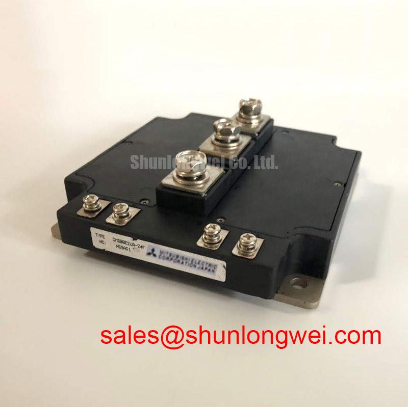
CM800E2UA-24F: Engineering a High-Efficiency 1200V/800A Dual IGBT Module
The Mitsubishi CM800E2UA-24F is a high-power U-Series IGBT module engineered for superior energy efficiency in demanding inverter applications. Featuring core specifications of 1200V, 800A, and a low typical Vce(sat) of 1.70V, this device is designed to minimize conduction losses and simplify the design of high-power phase legs. It directly addresses the critical engineering challenge of maximizing efficiency in large-scale motor drives and renewable energy systems by offering a significantly reduced on-state voltage drop, which lowers thermal load and improves overall system reliability.
Application Scenarios & Value
System-Level Gains in High-Power Motor Drives and Inverters
Best suited for high-power industrial motor drives and renewable energy inverters where minimizing conduction losses is a primary design objective. In the development of a 400kW+ Variable Frequency Drive (VFD) for heavy industrial machinery, for instance, engineers face the dual challenge of maximizing operational efficiency and managing significant thermal dissipation. The CM800E2UA-24F, with its robust 800A continuous current rating, provides the necessary power handling capacity. More critically, its low collector-emitter saturation voltage (Vce(sat)) of 1.70V (typ. at 125°C) directly reduces I²R losses during operation. This reduction in wasted energy translates into lower operating temperatures, allowing for more compact heatsink designs and enhancing the long-term reliability of the entire power conversion stage.
The module's integrated dual, or half-bridge, configuration further simplifies the design of an inverter phase leg. This reduces the bill of materials (BOM), minimizes layout complexity, and can decrease stray inductance compared to using discrete components. For systems requiring slightly lower current handling, the related CM600DX-24T offers a 600A capacity, while the CM800E2UA-24F is engineered for applications demanding maximum power throughput and efficiency in the 1200V class.
Key Parameter Overview
Translating Key Specifications into Reduced Conduction Losses
The electrical characteristics of the CM800E2UA-24F are optimized for high-current, high-efficiency switching. Below is a summary of key parameters that directly influence its performance in demanding power conversion systems.
| Parameter | Symbol | Value | Test Conditions | Engineering Value |
|---|---|---|---|---|
| Collector-Emitter Voltage | Vces | 1200V | Vge = 0V, Ic = 1mA | Provides a substantial safety margin for high DC-bus voltage applications, enhancing system ruggedness against voltage spikes. |
| Collector Current (DC) | Ic | 800A | Tc = 80°C | Enables control of very high power loads, suitable for large industrial motors and multi-megawatt inverters. |
| Collector-Emitter Saturation Voltage | Vce(sat) | 1.70V (Typ.) / 2.20V (Max.) | Ic = 800A, Vge = 15V, Tj = 125°C | A critical indicator of low conduction losses. This value directly reduces power dissipation, improving overall efficiency and easing thermal management requirements. |
| Total Power Dissipation | Pc | 4460W | Tc = 25°C, Per 1-element | Defines the module's capacity to dissipate heat, a crucial factor for calculating thermal limits and ensuring reliable operation under load. |
| Thermal Resistance (Junction-to-Case) | Rth(j-c) | 0.028 °C/W (Max.) | IGBT Part | Quantifies the efficiency of heat transfer from the semiconductor junction to the module's baseplate. A lower value indicates superior thermal performance. |
| Short-Circuit Withstand Time | tsc | ≥ 10µs | Vcc = 600V, Vge = 15V, Tj = 125°C | Ensures the device can survive brief, catastrophic short-circuit events without immediate failure, a critical safety feature for system protection. |
Frequently Asked Questions
Engineering Inquiries on Application and Thermal Design
How does the low Vce(sat) of the CM800E2UA-24F directly impact thermal management design?
The low Vce(sat) of 1.70V at 800A means less power is converted into heat during the 'on' state. For a thermal designer, this translates to a lower thermal load (watts) that needs to be dissipated. Consequently, it allows for the selection of a smaller, lighter, or lower-cost heatsink, or alternatively, provides greater thermal headroom to push the system to higher power densities without exceeding the maximum junction temperature. This is a crucial aspect of mastering IGBT thermal management.
What is the primary advantage of the dual (2-in-1) configuration in a three-phase inverter?
The dual IGBT configuration, also known as a half-bridge, integrates two series-connected IGBTs with their anti-parallel diodes into a single module. This package represents one complete phase leg of a standard three-phase inverter. The main advantage is design simplification: it reduces component count, simplifies the PCB and busbar layout, minimizes stray inductance between the switches, and often results in more predictable and reliable switching performance compared to using two discrete modules.
Can the CM800E2UA-24F be used in parallel to achieve higher current ratings?
Yes, IGBT modules like the CM800E2UA-24F can be connected in parallel for higher current output. However, successful paralleling requires careful design considerations to ensure balanced current sharing. This includes a symmetrical busbar layout, individual gate resistors for each module, and ensuring the Vce(sat) characteristics are well-matched. It is critical to consult the manufacturer's application notes from a source like Mitsubishi Electric for specific guidance on layout and gate drive design to prevent thermal runaway in one of the parallel modules.
What are the key considerations for the gate drive circuit for this 800A module?
For a high-current module like this, the gate drive circuit is critical. Key considerations include: providing sufficient peak gate current to charge and discharge the large input capacitance (Cies) quickly for efficient switching, using a stable gate voltage (typically +15V for turn-on and -10V to -15V for secure turn-off), and employing a Kelvin emitter connection to mitigate the effects of stray inductance in the emitter path, ensuring precise gate voltage control.
What does the 'U-Series' designation signify for this IGBT's performance?
The 'U-Series' refers to a specific generation of Mitsubishi's CSTBT™ (Carrier Stored Trench-Gate Bipolar Transistor) technology. This series is engineered to optimize the trade-off between conduction losses (low Vce(sat)) and switching losses. The U-Series is particularly focused on reducing Vce(sat) to enhance efficiency in applications where conduction losses are dominant, such as industrial motor drives operating at moderate switching frequencies.
An Engineer's Perspective
The CM800E2UA-24F represents a strategic component choice for power electronics engineers tasked with developing next-generation, high-efficiency power conversion systems. Its strength lies not just in its raw power handling capabilities, but in the nuanced performance gains offered by its low on-state voltage. This single parameter has a cascading positive effect on the entire system, influencing everything from energy consumption and thermal architecture to physical footprint and long-term operational reliability. When evaluating modules for high-power inverters, moving beyond headline voltage and current ratings to focus on loss characteristics, as exemplified by this device, is the key to achieving a truly optimized and competitive design.