

Content last revised on September 18, 2026
DFM300WXS17-A000 Thermal-Electrical Optimization: Thermal Interface Material Spreading and Practical Tuning
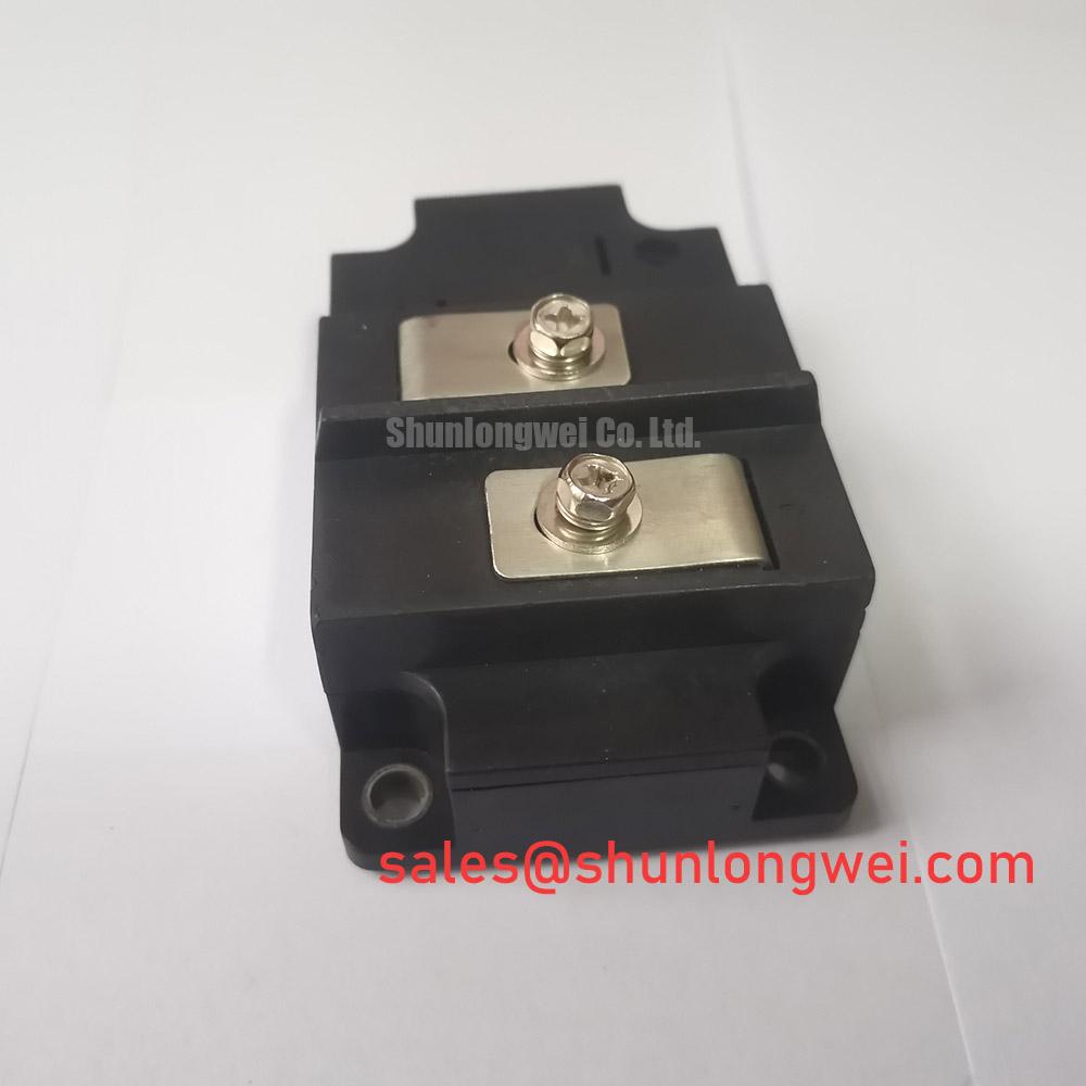
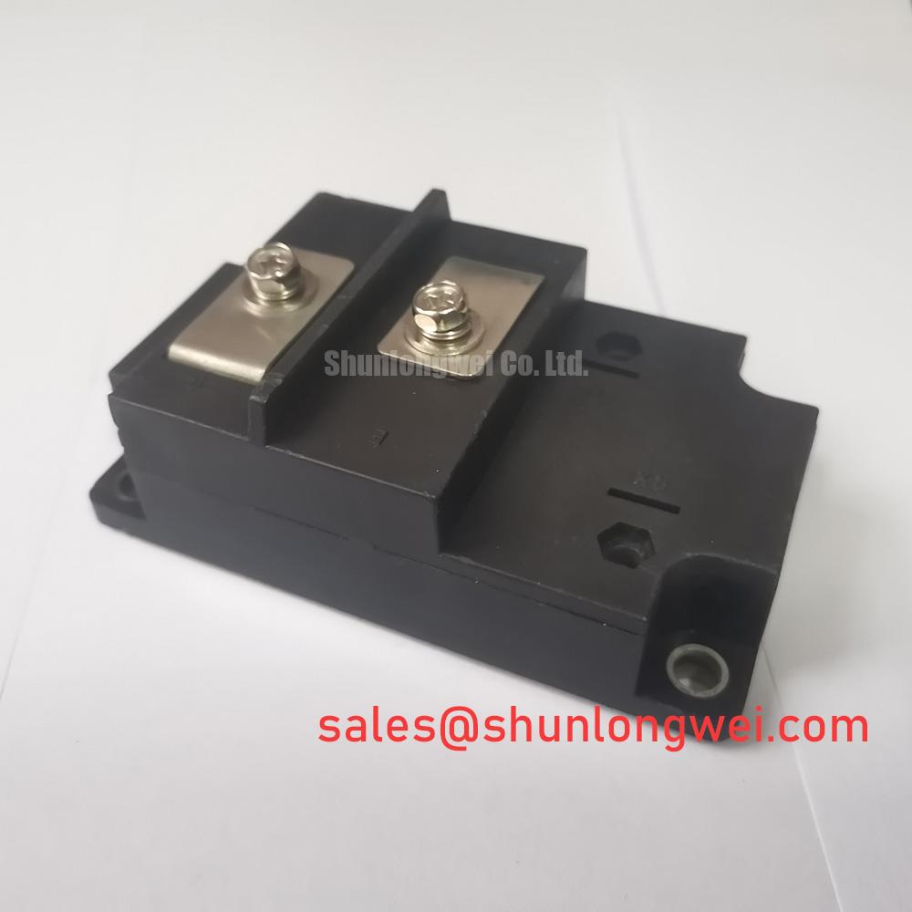
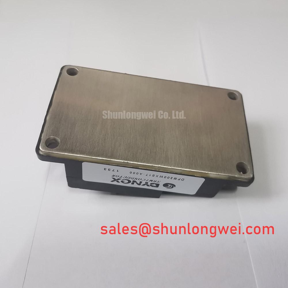
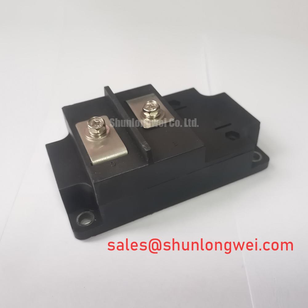
Verify the nameplate rating, inspect the high-power traction module for case or terminal damage, and check the heatsink contact surface before connecting the DFM300WXS17-A000 in a repair assembly.
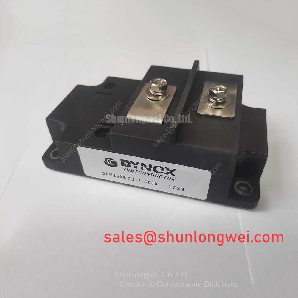
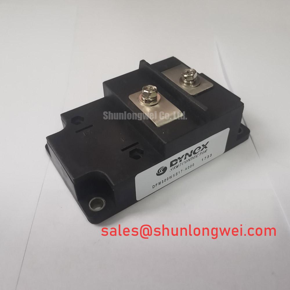
The Dynex DFM300WXS17-A000 is a High-Power Traction Module with an official rated voltage of 1700.0 V and an official rated current of 300.0 A. These values identify the principal electrical boundaries supplied for this product page. They do not replace the complete manufacturer datasheet, application circuit, protection coordination data, or the system engineer’s switching and thermal validation.
| Manufacturer | Dynex |
| Model | DFM300WXS17-A000 |
| Product category | IGBT Module |
| Rated voltage | 1700.0 V, Official Specification |
| Rated current | 300.0 A, Official Specification |
| Package | High-Power Traction Module, Official Specification |
For a replacement or commissioning inspection, begin with the copper baseplate and heatsink face. Both surfaces should be clean, flat within the limits defined by the applicable mechanical documentation, and free of particles that could create a local air gap. The supplied product information identifies the DFM300WXS17-A000 as a high-power traction module, but it does not provide a verified value for junction-to-case thermal resistance, transient thermal impedance, thermal paste thickness, or mounting torque. Those figures must therefore be taken from the applicable Dynex mechanical and thermal documentation before installation.
Thermal interface material should spread across the intended contact area without forcing the module body into distortion. A visible dry region, excessive paste at the edges, or a mounting surface that rocks during initial placement warrants correction before electrical commissioning. The purpose of the interface layer is to reduce contact irregularity between the module baseplate and heatsink; it is not a substitute for a properly prepared mounting surface or a controlled clamping method.
When evaluating a static var compensator or other power-conversion assembly, record the temperature at the module mounting region and compare it with the known-good phase positions under comparable loading. A rising contact temperature can be associated with several conditions, including airflow restriction, interface degradation, uneven clamping, current imbalance, or an upstream switching abnormality. Confirm the cause by checking the full thermal path rather than assigning the symptom to the module alone.
The official electrical identity remains the starting point: 1700.0 V rated voltage and 300.0 A rated current. Designers should calculate the actual junction temperature using the complete thermal resistance network and the relevant load profile, including repetitive pulses and transient conditions. The system heatsink, airflow, ambient temperature, switching frequency, and protection strategy determine the usable operating margin.
Fuse coordination also requires the manufacturer’s verified I²t data and the prospective fault current of the installation. No fuse I²t value is specified in the supplied product information, so a protective device should not be selected from the 300 A rating alone. Check the fuse clearing behavior, module surge capability, DC-link energy, and the system protection topology as one coordinated network.
⚠️ Maintenance Note: During scheduled service, monitor contact temperature trends and inspect the heatsink airflow path while checking that all terminal and mounting hardware remains within the manufacturer’s specified tightening procedure.
Preventing Spurious Faults: High-Frequency Switching Loss Dissipation Guidelines for DFM300WXS17-A000
Before high-frequency switching tests, confirm the wiring arrangement against the original schematic and identify every power, control, and auxiliary connection from the approved Dynex documentation. The available factory information confirms the module category, voltage rating, current rating, and package style, but it does not provide diode reverse-recovery current Irrm, reverse-recovery time trr, gate resistance, gate voltage, switching energy, or terminal pin assignments. These parameters should be verified from the detailed device datasheet rather than inferred from the model number.
In an inverter or other high-power switching installation, commutation behavior is affected by the complete circuit. Stray inductance, DC-link capacitor condition, transformer impedance, bus voltage, snubber design, fuse characteristics, and control synchronization can all influence current peaks and voltage overshoot. A fault indication during switching may therefore require a comparison of the gate command, collector-emitter voltage, phase current, and protection response on the same time base.
Use an appropriately rated differential voltage probe and current measurement method for commissioning work. A Hall effect sensor can provide isolated current observation in suitable industrial measurement arrangements; background information on this sensing principle is available from Hall Effect Sensors for Industrial Current Measurement. Probe bandwidth, grounding, insulation category, and physical loop placement remain system safety considerations determined by the test engineer.
DC-link capacitors and switched-capacitor branches should also be checked for condition and ripple stress. Equivalent series resistance influences heating and ripple-current behavior, and the general mechanism is described in this reference on capacitor ESR and ripple current. This external reference is not a Dynex specification for the DFM300WXS17-A000; use the original capacitor manufacturer’s data for acceptance limits.
To reduce unnecessary switching disturbance, designers should minimize parasitic power-loop inductance, keep gate-drive return paths controlled, and verify voltage overshoot against the module’s official voltage rating during switching tests. A metal-oxide varistor or other surge absorption network may be evaluated as part of the system protection design, but its clamping level, energy rating, repetition duty, and coordination with fuses must be established from the actual bus transient and approved component data.
For a neutral comparison of a related high-power device, engineers can review DIM800DCM17-A as a separate reference product. It should not be treated as an automatic substitute for the DFM300WXS17-A000; electrical topology, mechanical fit, gate-drive behavior, and protection coordination require independent verification.
DFM300WXS17-A000 Thermal-Electrical Optimization: Thermal Avalanche Margins during High Peak Practical Tuning
High-peak testing should begin with the device’s official application limits and the actual current waveform, not with the nominal 300 A rating alone. A sinusoidal 10 ms half-cycle surge test, if required by the equipment design, must be assessed using the manufacturer’s declared surge current and I²t values. Those surge figures are not included in the supplied structured parameters, so no ITSM value or repeated surge capability can be stated here as a product fact.
The test record should capture initial temperature, conduction duration, current peak, recovery interval, voltage reapplication, and the protection system response. Junction temperature during a short pulse cannot be judged accurately from heatsink temperature alone. The transient thermal impedance curve, case temperature, pulse width, duty cycle, and prior thermal history are needed to establish a credible peak junction-temperature estimate.
For battery energy storage interfaces or bidirectional DC-DC equipment connected to a reactive-power installation, repeated charge and discharge cycles can produce thermal cycling in the module and its mounting interface. Designers should evaluate the complete mission profile, including dwell time, current direction changes, cooling response, and capacitor or battery control transitions. No field lifetime or cycle-life value is provided for this Dynex model, so service-life claims require a documented test source.
During fault-current coordination, confirm that the fuse clears within the device’s permitted energy exposure and that the protection controller does not reapply voltage before the commutation or freewheel path is stable. The correct timing depends on the circuit topology and the verified Dynex switching and surge data. A static var compensator may also contain MOVs, reactors, capacitors, and bypass paths whose stored energy changes the stress seen by the module.
For a structured review of switching efficiency and high-voltage drive behavior, maintenance engineers may consult Unlocking Efficiency in Industrial Drives. That article provides general technical context and does not replace the product-specific Dynex datasheet for DFM300WXS17-A000 limits.
Field Diagnostics & Commissioning: High-di/dt Gate Firing: Pulse-Train Timing in DFM300WXS17-A000 Topologies
Commissioning should compare the firing pulse at the driver output and at the module terminals while the power stage remains controlled and safely isolated. The supplied product data does not confirm a gate pulse rise-time specification, a minimum gate-current slew rate, gate resistance, permissible gate-emitter voltage, or pulse-train timing. References to values such as diG/dt greater than 1 A/µs must therefore be treated as a test condition requiring confirmation from the original manufacturer documentation, not as an official rating for this model.
A stable firing sequence depends on pulse amplitude, pulse width, isolation delay, return-path impedance, controller synchronization, and the electrical state of the associated freewheel or commutation path. When several pulses are used, verify that the pulse train is intentional and that the driver does not continue firing during a protection trip or an abnormal capacitor voltage condition. An oscilloscope comparison with a known-good phase can help distinguish a control timing issue from a power-stage disturbance.
Inspect gate and power terminals for correct identification, secure mechanical attachment, and signs of heating. The available product record does not publish terminal numbering or tightening torque, so these details must be taken from the approved mechanical drawing or datasheet. Do not infer the connection order from another module with a similar current class.
During fault diagnosis, a missing or distorted pulse may indicate a driver supply problem, isolation fault, controller interlock, wiring impedance issue, or module-side abnormality. Measure the signal path in sequence and compare it with the approved circuit diagram. Avoid declaring the module defective from a single waveform observation without checking the driver, return path, protection interlock, and load condition.
After commissioning, retain the measured voltage, current, temperature, and firing-waveform records with the equipment maintenance file. This creates a practical baseline for later comparison when the SVC or switched-capacitor branch is serviced, while keeping the final operating limits tied to the manufacturer’s official documentation and the completed system validation.