

Content last revised on October 18, 2026
DIM3600ESM17-PT500 Thermal-Electrical Optimization: Practical Tuning of Planar Symmetrical Busbar Geometry
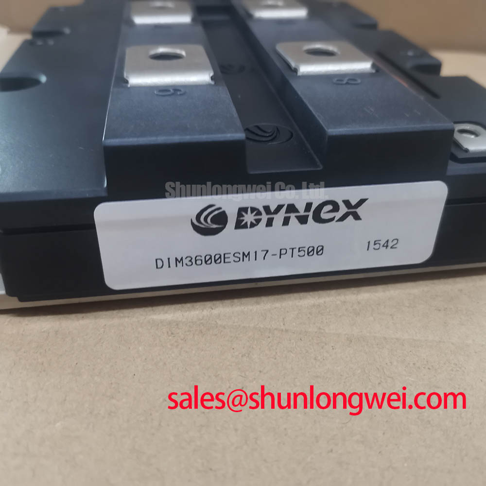
When a traction inverter shows excessive turn-off ringing, inspect the commutation loop before changing the gate drive. For the Dynex DIM3600ESM17-PT500, the official product ratings are 1700.0 V and 3600.0 A in a High-Power Traction Module package. These ratings identify the device class; they do not replace switching validation inside a complete converter.
The practical target is a compact, symmetrical power path between the module terminals, DC-link capacitors, and the associated switching elements. Unequal busbar paths allow one side of a commutation loop to carry more stray inductance than the other. During turn-off, the resulting voltage rise follows the familiar relationship between DC-link voltage, loop inductance, and current change rate. Engineers should therefore minimize the physical area of the high-current loop and verify the resulting peak voltage with a properly rated differential probe during controlled switching tests.
A planar busbar arrangement is useful because it can place opposing current paths close together, reducing magnetic field area and improving sharing between parallel conductors. The exact geometry remains system dependent. Clearance must accommodate the working voltage, transient overshoot, insulation system, contamination environment, and mechanical movement during service. The clearance around the module terminals should also remain free of sharp edges, loose hardware, and unnecessary control wiring that could increase capacitive coupling into the gate circuit.
Snubber selection should be treated as a measured damping task rather than a fixed accessory value. A capacitor that is too small may leave switching overshoot largely unchanged, while excessive capacitance can increase switching current demand and raise switching loss, depending on the snubber topology. The engineer should compare collector voltage, collector current, gate voltage, and case temperature under the intended switching sequence. Any snubber should be mounted with the shortest practical connection to the switching loop, with its pulse current capability checked against the converter operating waveform.
For high-speed rail and heavy freight locomotive traction inverter evaluations, the module can be considered only after the original electrical topology, cooling arrangement, gate driver behavior, and mechanical interface have been matched. A neutral comparison point is the FF650R17IE4P, which may assist engineers reviewing another high-power module reference, but pin arrangement, dynamic behavior, and mechanical fit must be checked independently rather than assumed from the current and voltage class.
Assembly Integrity & Layout Architecture: Preventing dv/dt-Induced Cross-Conduction in DIM3600ESM17-PT500 Applications
High dv/dt can couple energy into a nonconducting gate circuit and create unintended gate movement, especially when the turn-off loop shares inductance with the power commutation path. A dedicated low-impedance gate return, short driver connection, and active Miller clamp are useful design considerations for reducing the chance of cross-conduction. The driver must be evaluated with the actual module, gate resistor arrangement, isolation barrier, and switching waveform rather than treated as an interchangeable control block.
A negative gate bias can be considered where the driver and device documentation permit it, but the permitted gate voltage range must come from the applicable Dynex documentation and the final gate waveform must be measured at the module terminals. Excessive negative bias can create its own electrical stress, while an inadequate turn-off path may allow Miller current to lift the gate during the opposing switch transition. Designers should verify turn-off stability across temperature, DC-link conditions, load current, and the intended dead-time strategy.
The gate loop should be physically separated from high-current collector and emitter paths. Avoid routing the gate signal beside a fast switching node for long distances, and keep the driver reference tied to the correct module return point. Isolation devices used on industrial drive boards should be selected with suitable common-mode transient immunity for the switching environment. The complete assembly, rather than the isolator alone, determines compliance with system EMC requirements.
Thermal assembly begins with a clean, flat cooling surface and an even thermal interface layer. The interface material should fill microscopic surface irregularities without creating a thick, uneven film that increases thermal resistance. Mounting screws should be tightened progressively in the manufacturer’s specified sequence so that the baseplate seats evenly. The final torque must follow the module manufacturer’s mechanical instructions and the hardware specification; a generic fastener value should not be treated as a Dynex product limit.
💡 Pro Tip: Disconnect the DC link and control supply before inserting or removing gate-drive connectors, then confirm the absence of stored energy with an approved measurement procedure.
Field Diagnostics & Commissioning: Unpowered Multimeter Diode Screening for DIM3600ESM17-PT500
Cold bench screening should begin with the module isolated from the DC link, driver board, braking circuit, and any parallel semiconductor path. Keep each IGBT gate shorted to its corresponding emitter during main-terminal diode checks to prevent unintended gate charging. Use the digital multimeter diode-check function across the relevant main terminals in both polarities, recording the instrument indication rather than treating one universal forward value as a pass or fail threshold. The measured result can be affected by the internal circuit topology, antiparallel diode path, meter test current, and probe contact quality.
Where a corresponding conduction path exists in the same assembly, compare its forward response. A strong asymmetry deserves further investigation, particularly if it is accompanied by unstable readings, a short indication in both directions, or an open indication where a conduction path is expected. These observations are screening evidence, not a complete dynamic health assessment. Follow-up testing should use a controlled low-energy setup and appropriate current limiting before the DC link is energized.
Gate leakage screening requires the gate terminal to remain isolated from the driver and any clamp network, with any temporary gate-to-emitter short removed for the measurement. Measure gate-to-emitter behavior in both polarities with an instrument suitable for the device’s permitted gate conditions. Avoid applying a voltage that exceeds the documented gate limit simply to obtain a faster reading. If the result changes after handling, cleaning, or connector movement, inspect the interface for contamination, moisture, mechanical damage, or an unintended parallel circuit.
Before commissioning, document the module orientation, terminal identification, gate polarity, driver supply sequence, interlock state, and cooling contact. The first energized test should use controlled current and voltage conditions selected by the system engineer. Observe gate voltage at the module terminals, not only at the driver output, because the difference between those points can reveal common-emitter inductance, return-path movement, or probe reference error.
Current measurement is also important when a traction inverter shows unexplained imbalance. Hall, shunt, GMR, and TMR approaches each introduce different bandwidth, isolation, offset, and placement considerations. The general operating principles of GMR sensing are described in this GMR reference. The sensor choice must be evaluated against the complete converter’s current range, insulation coordination, response time, and control algorithm.
DIM3600ESM17-PT500 Circuit Protection & Reliability: Baseplate Curvature and Screw Loading
Thermal reliability depends on the contact condition between the module baseplate, interface material, and heatsink. Check both surfaces for burrs, embedded particles, warpage, and uneven contact marks before applying thermal compound. A thin, continuous interface layer is generally preferable to a thick deposit, but the suitable application method depends on the material, surface finish, flatness, and manufacturer instructions.
Baseplate curvature should be assessed as an assembly condition rather than corrected by forcing the module flat with excessive screw load. A suitable mounting pattern distributes pressure progressively and allows the baseplate to settle against the cooling surface. If the contact imprint is concentrated at one edge or corner, stop and inspect the heatsink flatness, mounting holes, washer arrangement, and screw sequence. Do not compensate for a mechanical mismatch by increasing torque beyond the specified limit.
Protection design should coordinate the fast semiconductor fuse, gate-driver fault response, and converter control interlock. The fuse’s breaking capacity and clearing characteristics must be checked against the actual prospective fault current, with its let-through energy assessed against the protected circuit’s withstand capability. An I²t value alone does not describe the full protection result because wiring inductance, fuse construction, fault duration, and module short-circuit withstand behavior also influence the event.
Desaturation protection can provide a controlled response to abnormal collector-emitter voltage, but the sensing network, blanking interval, soft turn-off profile, and isolation behavior must be tuned as one system. A hard gate interruption can create a new voltage overshoot, while an overly slow response can allow excessive semiconductor stress. The design engineer should verify the protection waveform using the intended DC-link and load conditions, with the fault energy constrained during commissioning.
For phase-controlled rectifier front ends, conduction-angle control and line-current shaping should be reviewed alongside the traction inverter. Harmonic mitigation may involve the converter topology, phase arrangement, input filtering, control timing, and grid impedance. The DIM3600ESM17-PT500 rating alone does not establish compliance with a particular power-quality or EMC limit. A complete protection review should also include isolation distances, discharge paths, precharge operation, and the response of the industrial drive controller.
Use the Field Engineer’s Handbook as a practical reference when organizing test records, fault capture, and component-level commissioning checks. For a replacement assessment, compare the original module’s terminal arrangement, gate requirements, thermal interface, protection coordination, and mechanical envelope against the proposed installation before applying full operating power.