Content last revised on September 10, 2026
Suppressing Acoustic Capacitor Buzz and EMI During PWM Backlight Investigation
Probe the original display assembly’s backlight supply and dimming control path with the panel disconnected before deciding that an audible buzz comes from the KG057QV1CA-G00 itself. A cabinet can transmit vibration from a nearby driver board, power inductor, ceramic capacitor, fan housing, or metal bezel, making a sound appear to originate at the LCD module. Listen with the enclosure open only after the equipment’s applicable electrical safety procedure has been completed, then compare the noise while brightness demand, video activity, and surrounding loads are changed independently.
The official product information identifies this unit as a Kyocera TFT LCD Display Module, but it does not establish a backlight technology, backlight ignition requirement, dimming format, PWM frequency range, backlight half life, or EMI performance value. Those attributes must remain tied to the original display documentation and the equipment’s backlight driver design. Do not apply CCFL ignition voltages, LED current settings, or a replacement dimming signal simply because they are common elsewhere in industrial display service.
Acoustic noise that changes with brightness control can indicate mechanical excitation within the host driver circuit or a control interaction between the controller board and its power stage. It can also accompany unstable supply regulation, loose chassis hardware, cable movement, or a stressed connector. Check the dimming waveform at the driver input, inspect the supply rail with an oscilloscope, and compare the result against a known good installation where available. A stable command signal and a changing output ripple pattern point the investigation toward the driver and its surrounding passive components rather than the LCD image path.
EMI investigation should separate radiated behavior from conducted noise. Inspect shielding continuity around the display cable, confirm that drain or shield terminations follow the equipment’s original architecture, and ensure that the cable does not run beside switching power conductors. Design Consideration: minimizing shared impedance between the display harness and high current switching paths helps prevent noise from coupling into image data, backlight control, or touch circuitry where a separate touch assembly is used.
Do not assign a backlight operating life figure to KG057QV1CA-G00 without an applicable manufacturer specification for the exact configuration. When a display becomes dim, intermittent, or visibly unstable, record the panel supply behavior, driver enable state, brightness command, ambient temperature, and image condition before replacing hardware. These observations provide a defensible maintenance record and reduce the chance of exchanging a display module when the fault remains in the host power or control circuit.
Thermal Cycling, Polarizer Condition, and Perimeter Gasket Inspection
Inspect the display perimeter, front surface, mounting land, and enclosure gasket immediately after a temperature related image complaint appears. Look for moisture traces, edge staining, pressure marks, changes in the apparent uniformity of a dark image, or an image response that improves after the cabinet reaches a stable temperature. These signs do not prove a single failure mechanism, but they help distinguish enclosure exposure, mounting stress, cable behavior, and display optical changes.
The supplied manufacturer information does not state an operating temperature range, storage temperature range, liquid crystal response time, adhesive construction, perimeter seal material, or thermal cycle qualification for KG057QV1CA-G00. It is therefore not appropriate to claim operation across a specific low or high temperature interval, or to assign a response lag threshold to this model. The system integrator should verify the required environmental limits from the original panel documentation and assess the installed enclosure as a complete assembly.
At low temperatures, liquid crystal behavior can appear slower, while condensation risk increases when equipment moves between cold and humid conditions. Design Consideration: allow the enclosure and display to stabilize thermally before judging image quality after a cold start. Rapidly applying power to an assembly carrying visible condensation can complicate diagnosis because connector contamination, surface moisture, and power supply behavior may occur together.
Gaskets deserve the same attention as the active display area. A gasket that has shifted, hardened, compressed unevenly, or accumulated debris can alter bezel pressure and create a path for dust or humidity. Clean only with materials approved for the equipment’s front window and enclosure surfaces. Avoid flooding the edge of the display with cleaning fluid, because liquid migration cannot be assessed from the external appearance alone.
⚠️ Maintenance Note: Check cabinet cooling paths, fan filters, and perimeter gasket condition during scheduled service so heat buildup and uneven bezel loading are found before image uniformity is evaluated.
For technicians assessing harsh installation conditions, The Ultimate Guide to Industrial TFT LCD Technology provides useful context for separating panel selection factors from enclosure level thermal and environmental controls. Kyocera’s own industrial TFT LCD display technology information is also relevant when comparing broad display technology families, although system acceptance must be based on the documentation for the installed panel and host equipment.
Flush Mount Bezel Integration and Gasket Shock Isolation
Release the bezel fasteners gradually in a cross pattern when a dark patch, bright edge, localized mura, or pressure sensitive image defect appears after service. Observe whether the optical symptom changes as clamp force is removed evenly. A display can look electrically normal while an uneven enclosure load affects visible uniformity, particularly when the front frame, gasket, mounting surface, or cable routing has changed during repair.
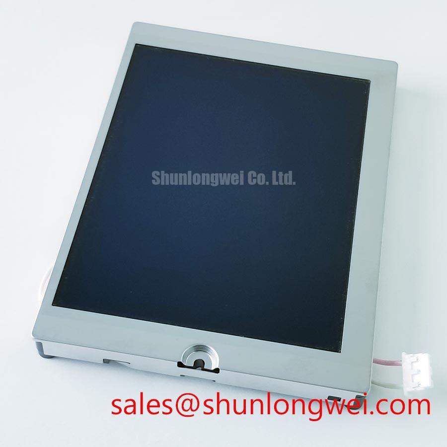
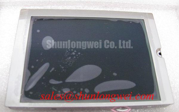
KG057QV1CA-G00 is identified as an industrial grade TFT LCD/HMI panel, yet the provided manufacturer information does not specify the outline dimensions, active area, mounting hole arrangement, bezel geometry, fastener size, torque limit, permissible panel deflection, or shock qualification. These mechanical values must not be inferred from a similarly sized display or from a cabinet cutout. Match the original mechanical drawing, bracket location, cable exit direction, and retention method before committing a replacement assembly to service.
Design Consideration: distribute retaining force around the display perimeter so that the chassis supports the intended mounting areas rather than pressing irregularly on the viewing surface. Tightening one corner fully before the others can distort the support stack, especially where a gasket has aged or where a painted enclosure edge is uneven. Use the host equipment manufacturer’s fastener sequence and torque requirement; the appropriate value is determined by the complete bezel, gasket, bracket, and panel stack.
Where a digital display interface is present, inspect the connector latch, contact alignment, cable bend radius, and shield arrangement before treating flicker or colored artifacts as panel defects. The supplied information does not identify the panel interface, connector type, logic voltage, timing format, or differential pair requirement. The system integrator should verify these details from the original panel documentation. A waveform comparison against a known good signal path is more reliable than assuming that a visually similar connector has identical pin assignments.
Potential evaluation in surgical navigation or ultrasound diagnostic display equipment requires special discipline. Such equipment may have controlled mechanical, cleaning, electrical safety, and image quality requirements beyond the characteristics stated for this TFT module. A panel replacement should preserve the original equipment configuration and proceed through the equipment owner’s established validation process. This is a compatibility assessment example, not a claim that KG057QV1CA-G00 is qualified for a specific medical system.
Kyocera also publishes information on silicon nitride substrates for power modules. That material concerns a separate power electronics product family and should not be used to infer display module insulation, electromagnetic compatibility, safety certification, or mechanical reliability characteristics for this LCD panel.
Surface Reflection Control and High Ambient Image Assessment
Inspect the switched off screen under the actual room lighting and then compare a full white, mid gray, and dark test image at the normal operator position. Record reflected glare, apparent contrast loss, viewing angle behavior, edge brightness, and any image inversion before changing the panel or adding a front filter. This test identifies whether the complaint follows ambient reflection, image generation, enclosure window condition, or a mechanical pressure effect.
The available manufacturer information confirms a TFT LCD Display Module but does not state the optical mode, viewing cone, contrast ratio, luminance, anti glare treatment, anti reflective treatment, sunlight readability, polarizer construction, or color performance. It is not appropriate to label the surface as AG or AR, claim a specific viewing angle, or assign direct sunlight contrast performance to KG057QV1CA-G00 without the exact optical specification.
Design Consideration: reflection control is determined by the complete viewing stack, including the display surface, any protective window, air gap, adhesive layer, bezel depth, room lighting angle, and operator position. A protective cover can improve cleanability or impact protection while also introducing reflections. Conversely, a matte treatment can reduce mirror reflections while changing perceived sharpness. Evaluate these tradeoffs using the installed enclosure rather than a bench observation of the bare display alone.
If the original equipment uses a touch layer, do not assume that touch technology, glove response, wet surface response, controller interface, or cleaning tolerance belongs to the KG057QV1CA-G00 display module. Verify whether touch sensing is part of a separate overlay and trace its cable to the host controller. Intermittent touch behavior may arise from the overlay, controller, grounding, front window contamination, or harness strain while the LCD image remains stable.
For high precision imaging terminals, evaluate readability with the installed user interface, normal illumination, prescribed cleaning condition, and the equipment’s intended viewing distance. Where the symptom is image washout, compare the display output to a known good source and inspect the enclosure window for haze, residue, scratches, or internal reflection. This method keeps the fault search focused on measurable display assembly conditions without assigning unsupported optical ratings to the panel.