

Content last revised on September 14, 2026
Localized Optical Compression and Dark Screen Field Inspection
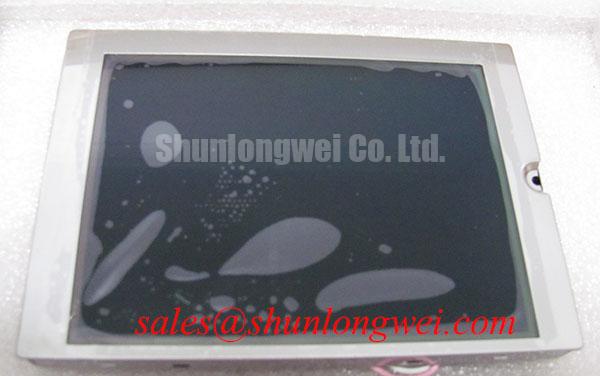
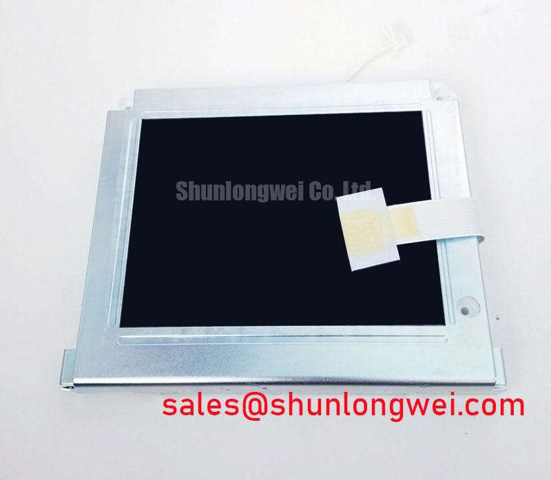
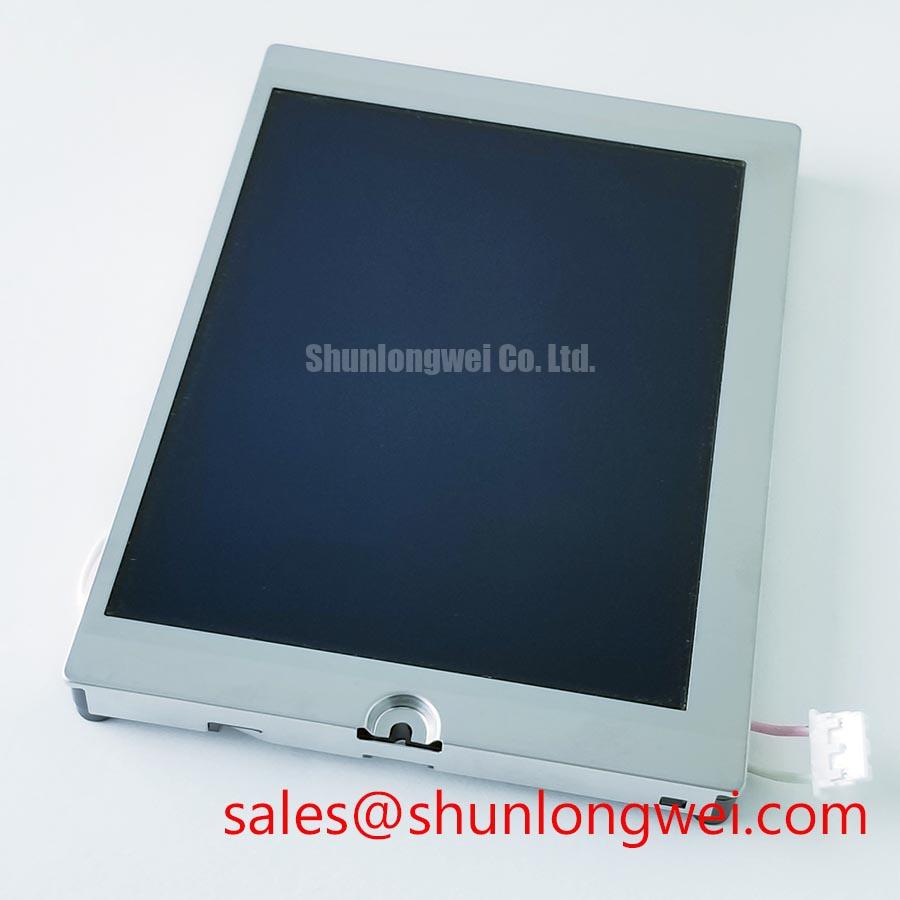
Dark-field inspection is useful for identifying pressure marks, uneven illumination, and localized optical mura. Drive the replacement panel with a known-good image source and inspect black, dark gray, white, red, green, and blue test fields at consistent ambient lighting. Any irregular bright or dark region should be compared with the panel before final fastening, since chassis pressure, uneven bezel contact, or connector strain can change the appearance after assembly.
The factory information supplied for this model does not specify bezel envelope tolerances, mounting-hole dimensions, light-guide construction, or allowable fastener torque. Those values must therefore be taken from the mechanical drawing or the original equipment assembly. As a general Design Consideration, fasteners should be tightened in a cross pattern with even contact loading, while the system designer verifies that the bezel is not pressing against the active optical area.
Signal quality also belongs in the same inspection. If the equipment uses TTL or LVDS signalling, verify the actual transmitter standard, clock behavior, data hold timing, and cable routing from the host documentation. These electrical characteristics are not confirmed as specifications for this display in the supplied data. For background on panel architecture and interface evaluation, consult The Ultimate Guide to Industrial TFT LCD Technology.
💡 Bench Tip: Use ESD protection and keep the flexible cable perfectly aligned before locking the connector; never insert or remove the display cable while the equipment is energized.
Backlight Driver Insulation and Safety Considerations
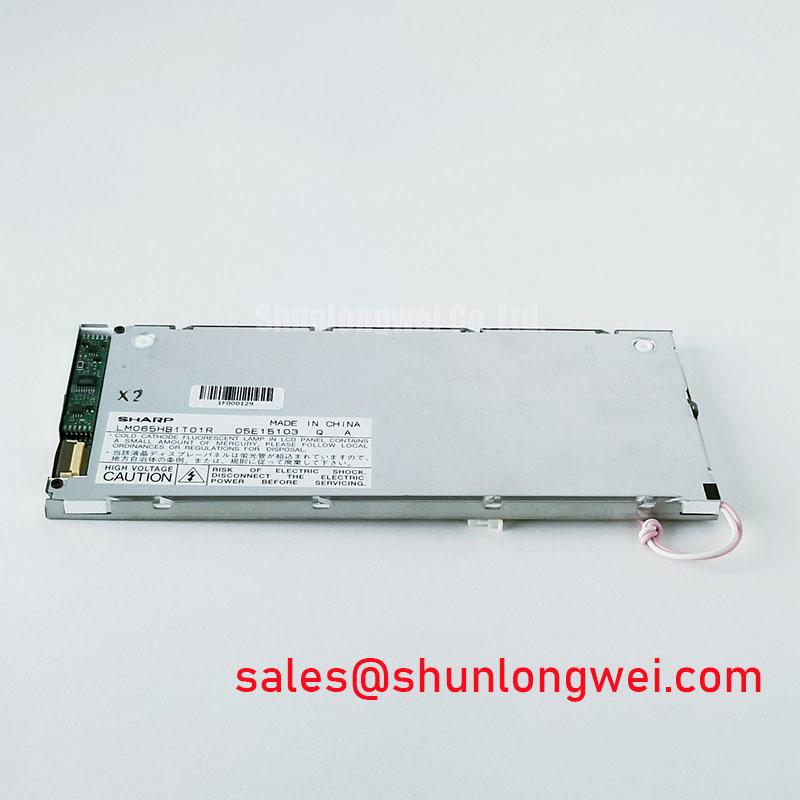
Do not assume a CCFL inverter or an LED backlight from the model number alone. The supplied factory record does not identify the backlight type, ignition voltage, driver topology, dimming method, or insulation rating. A replacement procedure should begin by identifying the original backlight driver and measuring its interface requirements from the equipment service documentation rather than applying an unverified high-voltage source.
For equipment such as a high-voltage substation protection or SCADA dispatch console, the display assembly may be positioned near switching and control circuits. A Design Consideration is to keep the panel wiring physically separated from high-voltage conductors and to inspect insulation, cable routing, and shielding as part of the cabinet-level safety review. Any secondary-coil or dielectric test must follow the equipment manufacturer’s approved procedure, test voltage, duration, and acceptance criteria.
Brightness ageing and backlight life are also system-dependent. No 50,000-hour half-life, MTBF, PWM ratio, or brightness retention value is provided for this specific model in the supplied official parameters. Do not publish or use those figures as product ratings without a Kyocera datasheet or an applicable test report. Kyocera’s industrial display technology information can be reviewed through its official industrial TFT-LCD resource.
Display Data Mapping Alignment with Even and Odd Channel Integrity
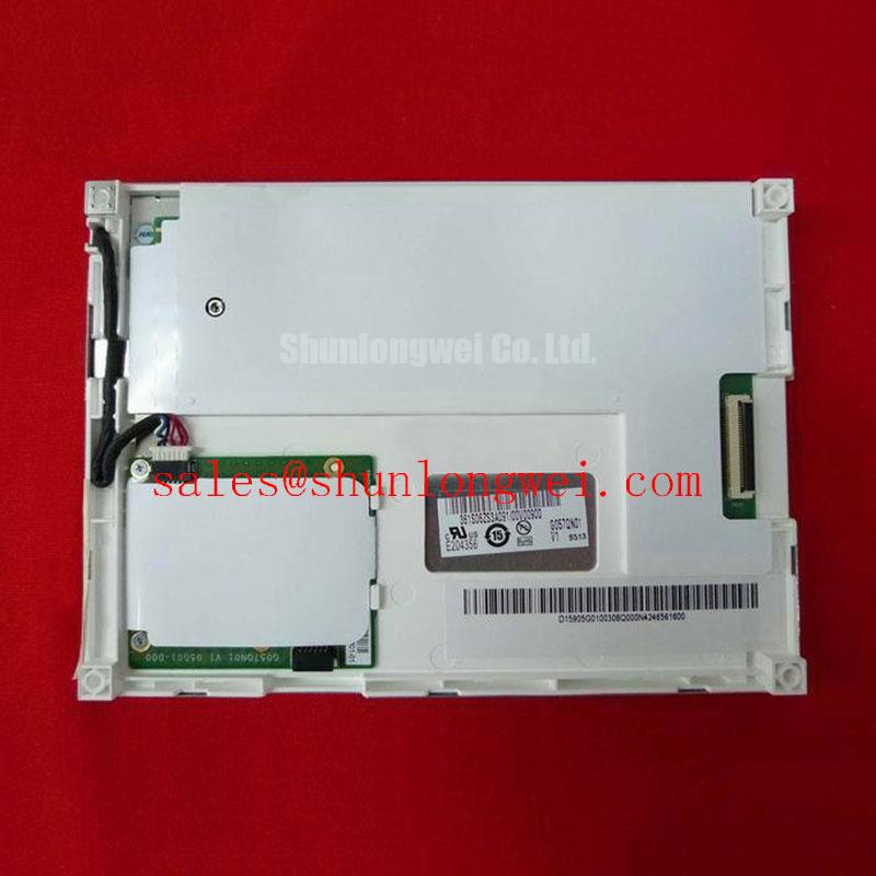
Before connecting the panel, identify whether the host uses LVDS, TTL, or another interface, then verify the connector pinout, pixel mapping, clock polarity, colour depth, and power sequencing from the original display documentation. The supplied information does not confirm VESA mapping, JEIDA mapping, logic voltage, rise-time limits, characteristic impedance, or timing windows for KG057QV1CA-G000.
Split-screen images, colour swaps, missing pixel groups, or unstable synchronization should be investigated by comparing the suspected panel path with a known-good cable and controller. An oscilloscope can help determine whether the clock and differential data pairs reach the display with the expected relationship, but the acceptance limits must come from the host and panel documentation. Routing should minimise unnecessary stubs and maintain a controlled differential path according to the system designer’s signal-integrity analysis.
Cold-environment operation requires the same discipline. Response-time changes, image persistence, and startup behavior may vary with the complete panel assembly and enclosure. The supplied factory data does not specify a sub-zero response-time curve, heater requirement, or temperature range, so the integrator should validate the complete console at its intended environmental limits.
Backlight Thermal Dissipation and Optical Preservation
Inspect the display with full-white and high-brightness test fields while checking for edge hot spots, uneven luminance, and localized colour changes. Do not add an aluminium spreader, thermal pad, or clamp based only on the model number. The official information supplied here does not define the LED rail layout, thermal interface, backlight power, luminance rating, optical coating, or long-term L70/B50 performance.
When this Kyocera panel is evaluated for a protection relay interface or SCADA dispatch console, the enclosure designer should account for internal heat sources, airflow, sunlight exposure, and the clearance around the display. Optical contrast under direct sunlight and anti-glare performance must be measured on the assembled unit because cabinet glass, viewing angle, surface treatment, and ambient reflections affect the result.
Kyocera also publishes information covering related semiconductor and substrate technologies through its official silicon nitride substrate resource; that material should not be interpreted as a specification for this LCD module. Final acceptance should be based on the verified panel identity, the original equipment interface, mechanical fit, and measured image performance.