

Content last revised on September 23, 2026
Interface, Timing, Connector & Display Drive Verification
Before applying power, verify the DMF5005NF-LY identification, inspect the LCD display module frame for corner deformation, confirm that the flexible cable is fully seated, and compare the host connector position with the original panel documentation.
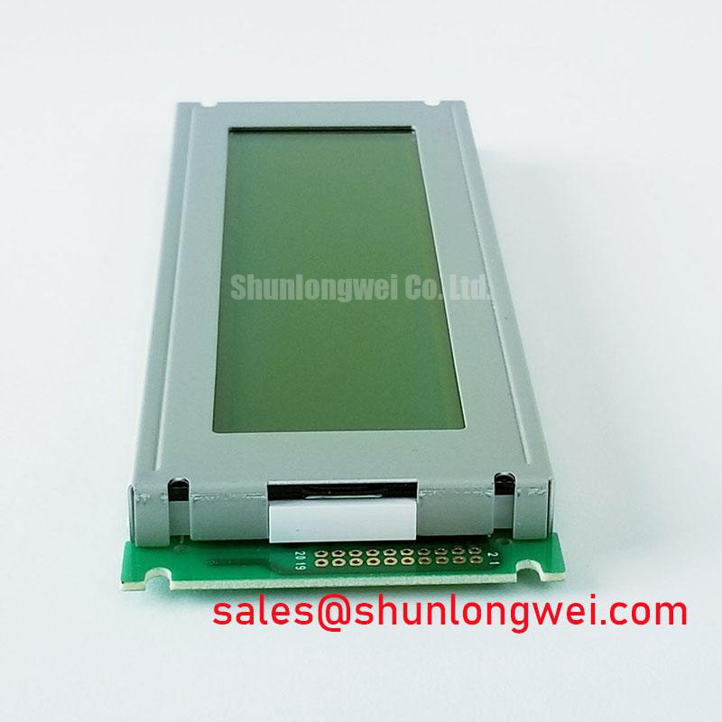
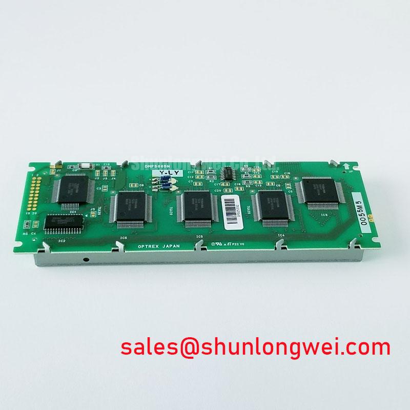
The DMF5005NF-LY is an LCD Display Module supplied under the Kyocera / OPTREX brand family. For repair and replacement work, the system integrator should verify the original equipment display documentation for electrical supply requirements, display-drive interface, connector assignment, timing definitions, backlight wiring, mechanical envelope, and controller compatibility.
| Item | Specification |
|---|---|
| Model | DMF5005NF-LY |
| Manufacturer | Kyocera / OPTREX |
| Product Category | LCD Display Module |
| Module Type | LCD Graphic Display Module |
During a service intervention, the most useful baseline is the removed original assembly. Record its label data, connector orientation, cable routing, mounting points, visible gasket condition, and the host controller behavior before disconnecting the panel. A display module replacement should be treated as an interface verification task rather than a simple mechanical substitution, especially where the panel is part of an industrial HMI, telematics terminal, control cabinet display, or operator console.
The connector count and pin arrangement must be confirmed from the original panel documentation and host-board schematic. These documents should determine the actual connector type, pin numbering, supply rail, display-drive signals, enable signals, and backlight connections. Similar connector counts do not establish electrical compatibility.
For an LCD replacement, the first electrical check should establish whether the host controller provides the logic supply required by the original panel. The system integrator should verify the required supply voltage from the original panel documentation rather than assuming a 3.3 V or 5.0 V interface. Power sequencing is equally important. A panel may remain blank, show unstable startup behavior, or display intermittent image artifacts when the supply, enable, data, or backlight sequence does not match the original system design.
Design Consideration: display interface signals require suitable routing, grounding, and a stable return environment through the cable and host PCB. The correct implementation must be verified against the equipment controller, cable assembly, connector geometry, and original display documentation. The technician should inspect whether the replacement cable is sharply folded, trapped beneath the bezel, or routed beside high-current switching conductors.
The display-drive format and timing also require confirmation at the controller level. Incorrect configuration can present as a blank display, incorrect image data, unstable operation, or an image that is active but visually unusable. These symptoms do not prove one single cause. They may indicate an interface mismatch, incorrect timing, a poor connector contact, a damaged cable, or a controller-side configuration error. Measurement at the panel connector, together with comparison against a known-good signal path, can help isolate whether the required signals are present.
Cold ambient conditions deserve special attention when the equipment operates in outdoor industrial locations. Liquid-crystal response can slow at sub-zero temperature, causing transitions to appear delayed or smeared. This is a physical temperature effect, not necessarily a fault in the display module. Where the equipment has a heater, enclosure heater, or controller-managed preheat routine, designers should verify that its operation follows the original equipment thermal strategy before judging display response during cold startup.
🔧 Bench Diagnostic: Disconnect and reconnect the display cable only after the host power is fully removed, because live connector handling can expose sensitive interface circuitry to unintended transients.
Optical Stack & Thermal Buckling Prevention under Continuous Full-Duty Operation
The DMF5005NF-LY should be installed with a flat, clean support structure that does not concentrate force along one portion of the display edge. Although the internal optical construction is not specified here, uneven external chassis pressure and local heat concentration can contribute to visible non-uniformity, edge brightness variation, or optical distortion during long screen-on duty.
Design Consideration: narrow display edges should receive mechanically even support from the host bezel or heat-spreader arrangement. The goal is to avoid a situation where one small frame area absorbs most of the chassis load or acts as a thermal hot spot. The system engineer should validate the completed assembly under the actual enclosure temperature, duty cycle, vibration condition, and display brightness setting used by the equipment.
Continuous operation also calls for practical attention to cabinet airflow. Dust accumulation around fan intakes, rear ventilation slots, controller boards, and backlight-driver areas can increase enclosure temperature even where the display itself is not visibly damaged. A blocked airflow path may affect several elements in the HMI assembly, including the panel, controller, power conversion stage, and cable insulation.
⚠️ Maintenance Note: During scheduled service, inspect ventilation paths, bezel gaskets, and display-frame contact surfaces for dust buildup, hardening, displacement, or moisture tracks before returning the equipment to service.
Where high electromagnetic noise is present, display instability should not be attributed to the LCD module alone. Cable continuity, grounding continuity, shield termination where applicable, cable routing, and host controller power quality all deserve inspection. A cable running alongside motor leads, contactors, inverter output conductors, or poorly filtered switching supplies can introduce conditions that are not reproduced during a quiet workbench test.
For broader background on panel technology, integration questions, and service terminology, see The Ultimate Guide to Industrial TFT LCD Technology. The guidance is useful when evaluating display behavior across changing industrial temperatures and enclosure conditions, while the original equipment documentation remains the controlling reference for the DMF5005NF-LY installation.
Preventing Localized Optical Non-Uniformity on Dark Screen Fields
Dark screen fields are often the most revealing condition for mechanical stress in an assembled display. Before final fastening, power the panel where safe to do so and observe a dark or low-level image while the bezel is positioned without load. After fastening, compare the screen again. A visible change after bezel tightening can indicate that the chassis, seal, mounting land, or cable route is applying uneven pressure to the display assembly.
The external metal frame and surrounding bezel should remain planar through the mounting cycle. Do not use the display itself to pull a distorted enclosure into alignment. If the surrounding panel cutout is twisted, bowed, or affected by cabinet vibration, correct the host structure before relying on fasteners to close the gap. This reduces the likelihood of local compression near corners and narrow edges.
Design Consideration: where an M3 fastener pattern is used by the host equipment, a cross-pattern tightening method helps distribute load more evenly. The commonly referenced 0.35 to 0.45 N·m range is a general industry starting reference for suitable M3 hardware and is not an official mounting torque specification for the DMF5005NF-LY. Final torque must be determined by the original enclosure design, screw type, thread engagement, mounting feature, gasket behavior, and equipment validation procedure.
Do not place thick labels, cable ties, rigid adhesive blocks, or unapproved foam pads behind the active display area. These additions can create isolated pressure points that only become apparent after thermal expansion, vibration exposure, or enclosure closure. If a sealing gasket is necessary for dust or moisture control, verify that it contacts the intended bezel land rather than the panel viewing area or an unsupported section of the frame.
In industrial HMI cabinets, humidity control matters as much as screw tension. A cold panel brought into a warm, humid maintenance environment can accumulate condensation if the enclosure is opened too quickly. Allow the assembly to stabilize under the site maintenance procedure, inspect connector cavities for moisture, and ensure that protective seals are seated without folds or trapped debris.
Heavy mining shovel and earthmoving equipment telematics displays are examples of applications where engineers may evaluate industrial LCD modules, subject to confirmation of vibration, enclosure sealing, controller interface, mechanical mounting, and environmental requirements. This is a compatibility assessment example only and does not represent an application-specific factory approval for the DMF5005NF-LY.
Preventing Frame Lag & Image Smearing in Low-Temperature Outdoor Industrial Facilities
When an industrial display has been stored or operated at low temperature, begin diagnosis by separating image-generation faults from temperature-related optical response changes. Confirm that the host controller is producing the expected image data, then observe whether the display follows the image slowly, leaves apparent motion trails, or recovers as the assembly reaches a more stable temperature. These observations can support a temperature-related assessment, but they do not replace confirmation of the equipment’s approved operating conditions.
At low temperature, liquid-crystal viscosity can increase and visible transition time can lengthen. A display may therefore appear to have frame lag even when the controller is operating correctly. In a cold outdoor installation, the system engineer should verify whether the original equipment uses an enclosure heater, startup delay, thermal sensor, brightness limitation, or controlled warm-up sequence. Those system-level measures are determined by the original equipment design and should not be improvised from generic panel guidance.
Thermal cycling also affects the surrounding mechanical assembly. Cable jackets, connector locks, gasket materials, mounting brackets, and panel-frame interfaces can move differently as temperature changes. During preventive maintenance, inspect the flexible cable or display harness for sharp bends, unsupported vibration loops, abrasion at metal cutouts, and incomplete connector locking. A cable that remains electrically connected on a bench may still become intermittent when the machine experiences vibration or temperature movement.
For PWM-controlled backlights, the host controller and original panel documentation should define the acceptable dimming method and frequency. A PWM range of 200 Hz to 1 kHz is often discussed as a general display-integration consideration, but it is not an official operating specification stated here for the DMF5005NF-LY. Engineers should verify visible flicker, camera interaction, dimming range, electrical noise, and thermal behavior using the actual backlight driver and equipment controller.
Where outdoor cabinets experience repeated cold starts, maintain a clear diagnostic record: ambient condition, enclosure temperature, startup time, screen behavior, controller status, cable condition, and any recovery after stabilization. This approach avoids assigning a single cause to image smearing or delayed response and gives maintenance teams useful evidence when comparing the DMF5005NF-LY installation with the original display assembly.