

Content last revised on September 14, 2026
Mitigating Gray-to-Gray Response Time Escalation during Cold-Start Machine Power-Up
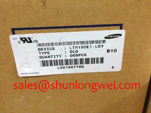
| Model | LTM190E1-L03 |
| Manufacturer | Samsung |
| Product Category | Industrial Grade LCD/HMI Panel |
| Display Technology | TFT-LCD Active Matrix Color Display Module |
| Specification Status | Basic identification verified; detailed specifications require confirmation from the original panel documentation |
Measure the first visible gray transition immediately after a cold start, then compare the panel image against a known-good signal source while recording the ambient condition and the time required for the image to stabilize. The LTM190E1-L03 is identified here as a TFT-LCD active matrix color display module; the supplied factory data does not state a guaranteed gray-to-gray response time or a confirmed operating temperature range, so cold-start performance must be validated against the original panel documentation and the host equipment test limits.
Liquid crystal response can become slower as temperature falls because the liquid crystal medium responds less quickly to changes in the applied electric field. This is a general display engineering consideration, not a model-specific performance guarantee. During evaluation, use moving gray patterns, black-to-white transitions, and mid-level gray screens rather than relying on a static desktop image. Record ghosting, trailing edges, incomplete transitions, and any temporary contrast change during the first minutes of operation.
For equipment such as a harsh marine radar or navigation bridge console, the enclosure, front window, heater system, and airflow path may influence the panel temperature. Designers should verify the required environmental range from the original LTM190E1-L03 documentation and confirm that any heater or defogging system warms the display evenly. Localized heating can create visible luminance differences or mechanical stress, particularly when the front assembly and metal mounting frame expand at different rates.
If the installed system uses PWM backlight control, verify the actual control method from the panel and host documentation rather than assuming LED or CCFL architecture. A PWM frequency in the 200 Hz to 1 kHz range may be evaluated as a general design consideration when checking visible flicker and audible interaction with mechanical structures, but it is not an official specification for this module. Measure duty-cycle linearity with the intended backlight driver and inspect the display through a camera as well as with the naked eye.
Perimeter sealing should also be assessed at the assembly level. The supplied product data does not confirm a particular epoxy formulation, optical-bonding construction, or ingress-protection rating. For a salt-air installation, engineers should inspect the bezel interface, gasket compression, venting strategy, and cable entry points after thermal cycling. The panel itself should not be treated as independently certified for marine environmental exposure unless the complete assembly documentation states that qualification.
Long periods of fixed HMI content can leave temporary image retention or produce uneven aging in the complete display system. Use screen-blanking, moderate brightness settings, and periodic content changes where the control application permits. These are system-level design considerations and should be verified through the actual duty cycle, luminance setting, and enclosure temperature rather than presented as a guaranteed life result for the LTM190E1-L03.
20-Pin/30-Pin Differential LVDS Timing, Pixel Clock and Skew Compensation
Probe the host logic supply, panel enable sequence, pixel clock, and differential data activity at the connector before interpreting split-screen or white-screen symptoms. The supplied factory information does not confirm whether this specific module uses a 20-pin or 30-pin interface, nor does it provide a pinout, logic voltage, pixel clock limit, JEIDA or VESA mapping, or timing table. Match the replacement panel to the original cable, connector keying, pin assignment, and controller configuration.
A connector that appears mechanically similar may still carry a different power, ground, enable, or differential-pair assignment. Photograph the original cable orientation before removal, identify pin one from the panel and controller markings, and check continuity with power disconnected. The system integrator should verify the required supply voltage from the original panel documentation rather than assuming that the interface uses 3.3 V or 5.0 V.
Power sequencing is equally important. Observe the logic rail and display enable signal with an oscilloscope during startup and shutdown, looking for premature enable activity, excessive ringing, or a rail that collapses slowly after power removal. The supplied data does not specify a rise-time window such as 0.5 ms to 10 ms for this model. Any such timing must come from the original electrical specification or be established by controlled system testing.
When differential LVDS routing is used by the host system, maintain a continuous reference plane, avoid unnecessary stubs, and keep each pair coupled through the connector and cable transition. A nominal 100 ohm differential impedance is a common interface design consideration, not a confirmed LTM190E1-L03 specification. The actual cable construction, controller output standard, termination arrangement, and receiver requirements determine the acceptable margin.
Incorrect JEIDA or VESA mapping can produce color errors, reversed tonal order, vertical bands, or a divided image. Confirm the mapping in the controller firmware and compare it with the original panel configuration. Pixel clock frequency, horizontal timing, vertical timing, data enable polarity, and synchronization behavior should be checked as a complete set. Changing only one timing field can conceal the original fault while creating a new compatibility problem.
At low ambient temperature, gray transitions may lengthen even when the LVDS waveform is clean. Separate signal-integrity observations from optical response observations by checking the differential eye or edge quality while displaying a moving test pattern. If the waveform remains consistent but image motion appears slow, investigate temperature and panel response. If the waveform shows intermittent activity, unstable common-mode behavior, or pair-to-pair timing variation, investigate the cable, connector lock, grounding, and controller output.
For systems with long cable runs or strong electrical noise, engineers should verify skew against the receiver margin specified by the controller manufacturer. A value such as 50 ps may be used only where the interface documentation defines that budget; it must not be assigned to this module without source data. Factory EMC compliance cannot be claimed for the display module independently of the complete radar, console, or HMI assembly.
High-Nits Edge-Lit LED Rail Thermal Dissipation and Optical Preservation
Use a calibrated luminance meter and thermal camera to map the screen and bezel temperatures at the intended brightness before changing the backlight drive. The supplied factory parameters identify the LTM190E1-L03 as a TFT-LCD active matrix color display module but do not confirm a backlight type, brightness rating, optical bonding construction, light-guide material, L70 or B50 life value, or edge-rail geometry.
Localized bright or dark regions should first be separated into optical, electrical, and mechanical categories. Compare a full-white field, black field, red, green, and blue screens, then repeat the inspection at more than one brightness setting. A luminance change that follows brightness control may involve the backlight or its driver, while a fixed geometric shadow may involve the optical stack, bezel pressure, contamination, or viewing-window alignment. These observations narrow the test path but do not establish a single failure cause.
If the original assembly uses edge-lit LEDs, an aluminum spreader rail may be evaluated as a general thermal design consideration. Its effectiveness depends on contact pressure, interface flatness, airflow, enclosure conduction, and the driver current profile. Do not assume that a replacement rail, thermal pad, or adhesive is compatible with the original optical stack. The system engineer should verify hot-spot temperature and luminance uniformity under the complete mechanical installation.
The supplied data does not establish PMMA light-guide construction or yellowing behavior for this model. Avoid describing a particular internal light-guide material as a confirmed feature. Instead, inspect the panel for color shift, edge brightening, haze, pressure marks, and nonuniform diffusion after the display reaches thermal equilibrium. Salt deposits, cleaning chemicals, trapped moisture, and excessive front-window pressure can all affect the visible result at assembly level.
High brightness in a sunlit bridge console may tempt operators to increase the backlight drive beyond the original setting. That change should be treated as a system adjustment requiring thermal, optical, and electrical validation. Verify driver output, connector temperature, enclosure heat rejection, and the panel’s documented limits. No independent L70 or B50 operating-life claim should be made without the manufacturer’s test conditions and source document.
Where differential data lines pass close to a backlight driver, route them to reduce coupling with switching nodes and return currents. A controlled differential path can reduce the risk of display artifacts, but the necessary impedance, spacing, and skew are determined by the controller, cable, and board stack-up. Inspect the image while varying backlight load to determine whether the disturbance follows optical brightness or digital activity.
For wider reliability context, engineers evaluating display integration can consult The Ultimate Guide to Industrial TFT LCD Technology. References concerning polyimide insulation, such as Polyimide Film High Voltage Dielectric Insulation in Power Circuit Assemblies, and partial discharge, such as Partial Discharge Detection in High Voltage Power Modules, relate to high-voltage assembly practice rather than serving as specifications for this LCD module.
Flashlight Dark-Shadow Optical Diagnostic to Isolate Logic versus Backlight Failure Modes
Display a full-white test field, darken the surrounding area, and place a flashlight at approximately forty-five degrees to the front surface while observing whether faint image content remains visible in an apparently unlit region. This dark-shadow test helps distinguish a logic or image-generation problem from a backlight-path problem, but it cannot by itself identify a specific internal defect.
Run the primary-color sequence with full red, full green, full blue, and white screens, checking for fixed lines, rectangular regions, missing columns, abnormal color channels, and areas that respond to image changes. A visible image under external illumination can indicate that image data is reaching at least part of the liquid crystal layer while the backlight path is not producing normal illumination. A completely inactive image requires additional checks at the host output, panel supply, enable signals, and connector.
Use a second step with a known-good controller or signal source only when the electrical interface, timing, and connector assignment have been verified. A controller mismatch can create symptoms that resemble panel damage. Check cable seating, lock engagement, pin-one orientation, ground continuity, and signs of contact contamination with power removed. 💡 Bench Tip: Disconnect power before inserting or removing the panel cable, protect the work surface against ESD, and close the connector lock only after the flex cable is fully aligned.
The third step is a moving-pattern test at several gray levels. Observe whether a line remains fixed in the same physical location, follows the image content, or changes after gentle thermal stabilization without applying pressure to the glass or flexible cable. Mechanical probing can create temporary contact changes and may worsen an existing connection fault, so use noncontact observation and oscilloscope measurements wherever possible.
A flashlight shadow that reveals stable image information while the screen appears dark can direct attention toward the backlight supply, enable signal, driver circuit, fuse path, or illumination assembly. It does not prove that the LCD cell, bonded driver, or cable is healthy. Conversely, a persistent line or block through multiple primary-color patterns may require panel-level evaluation, but a definitive internal fracture diagnosis requires suitable inspection equipment and manufacturer-level failure analysis.
Cold-start testing should be repeated after the optical diagnostic because low temperature can extend gray-to-gray transitions and make a healthy image appear slow or smeared. Record the ambient condition, startup sequence, brightness command, and time to stable operation. If a heater strip is present in the equipment, verify its control behavior and temperature distribution independently; the supplied LTM190E1-L03 data does not establish a heater requirement or a heater-control specification.
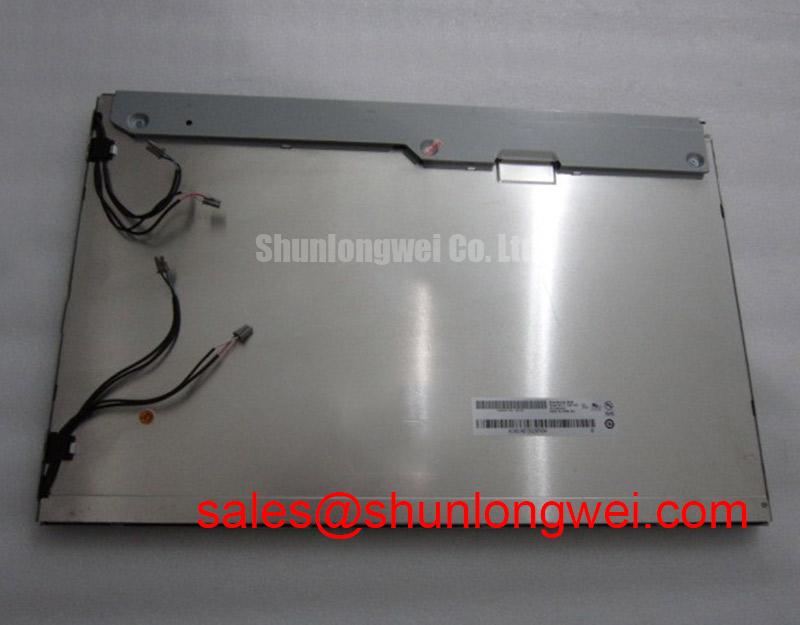
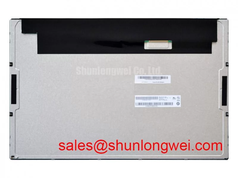
For procurement and repair release, compare the replacement against the removed unit using the confirmed model marking, connector arrangement, mechanical mounting points, display image, color sequence, brightness response, and startup behavior. The model is categorized as an Industrial Grade LCD/HMI Panel with a TFT-LCD Active Matrix Color Display Module construction. Interface, environmental, optical, and timing values not provided in the factory parameter set should remain open verification items for the equipment engineer.