Content last revised on September 11, 2026
EL4836HB Inspection and Identification
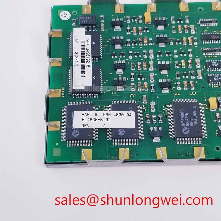
Inspect the EL4836HB label, display face, perimeter frame, and connector area under diffuse bench lighting before applying power; record any edge deformation, surface pressure marks, loose hardware, or cable-seat irregularity that could affect installation. This unit is identified as a Planar industrial-grade TFT-LCD display module. The supplied factory information does not state resolution, active area, interface type, supply requirement, luminance, viewing angle, environmental ratings, or mounting dimensions, so these items must be confirmed against the original equipment documentation before replacement or new integration.
| Identification Item | Declared Information |
|---|---|
| Model | EL4836HB |
| Manufacturer | Planar |
| Product Category | Industrial Grade LCD/HMI Panel |
| Module Type | TFT-LCD Display Module |
| Specification Status | Identification data available; detailed specifications require verification |
Heat Spreader and Thermal Interface Considerations along Narrow Display Edges
During enclosure inspection, check whether the EL4836HB is held by a narrow peripheral bezel, rear support rails, or a combination of both. A display panel can be affected by heat sources located outside the module itself, including controller boards, power conversion assemblies, sealed operator-station housings, and direct solar loading through a protective window. The supplied factory information identifies the EL4836HB as a TFT-LCD module but does not specify its allowable thermal interface location, heat-spreader dimensions, optical coating, sunlight contrast ratio, or backlight lifetime. Those characteristics must not be assumed from the product category alone.
Design Consideration: Where an enclosure places heat near narrow display edges, system integrators should assess the mechanical path and air path around the panel rather than allowing a metal rail or thermal pad to bear against an unverified optical or active-area boundary. A heat-spreading member should support the enclosure design without concentrating force on the display frame. Thermal behaviour needs to be checked at the installed operating position, with the actual protective glass, gasket, controller, and ambient conditions present.
For a hazardous petrochemical Zone 2 operator station, the display is only one part of the finished assembly. The suitability of the completed station depends on its enclosure, sealing, power architecture, cable entry system, and applicable site requirements. The EL4836HB itself should not be represented as providing an explosion-protection or system certification unless that status is documented by the relevant equipment approval records.
When a screen appears less readable under high ambient light, separate the observation into reflected glare, reduced backlight output, incorrect display timing, contamination on the cover window, and changes introduced by the enclosure. Do not attribute the result to an anti-glare treatment or a particular contrast figure unless those features are confirmed in original Planar documentation. For broader enclosure and integration checks, see Industrial Display & HMI Solutions.
Preventing Localized Light Guide Plate Compression Warp on Dark Screen Fields
With power removed, place the panel on a clean, flat, ESD-controlled bench and inspect dark fields at several viewing positions after installation. Localised bright or dark regions can be associated with bezel loading, panel-frame distortion, uneven gasketing, a cover-window contact point, or backlight and signal conditions. A visual result alone does not establish a single cause, and no internal light-guide construction or fastening limit is declared in the provided EL4836HB factory data.
Design Consideration: Use the host equipment’s documented mounting pattern and hardware procedure. Tighten retained fasteners in a balanced cross pattern where the chassis design calls for it, while avoiding point loading near the active display region. Mounting torque, bezel clearance, gasket compression, and support locations are system-specific values that should be obtained from the original equipment drawing or validated by the responsible mechanical engineer. Do not apply generic M3 torque values as an EL4836HB factory requirement.
💡 Bench Tip: Disconnect power and use ESD controls before handling the flex connection, then keep the cable square to its connector and fully aligned before closing the retention feature.
For incoming assessment, use full-field black, white, red, green, and blue test images after the approved interface and power sequence have been verified. Compare the result with a known-good signal path where available. Photographing the same test pattern at a consistent exposure can help distinguish repeatable display non-uniformity from changing reflections caused by the work area.
If an existing repair requires evaluation of a different display item, NL192108JC18-03ND can be reviewed as a separate sourcing candidate. Its mechanical outline, optical performance, electrical interface, timing, pin assignment, mounting geometry, and original-equipment compatibility must be independently verified; no direct substitution relationship is established by the EL4836HB identification data.
Single Vertical Hairline Defect Inspection
Start a line-defect check with a controlled sequence of full-screen primary red, green, and blue images, followed by white and black fields. Observe whether a vertical line remains at the same physical location through every colour field, whether it changes with the input source, and whether it is visible before the panel reaches normal operating state. This establishes evidence for further diagnosis without assigning the defect to a specific internal structure.
A flashlight inspection at an oblique angle can help reveal surface contamination, cover-window marks, pressure impressions, and reflections that are difficult to see under direct bench lighting. It should be treated as a screening method, not as proof of a backlight or driver fault. If the line varies when a known-good cable or controller path is used, inspect connector retention, cable condition, ground continuity, source timing, and the host controller before deciding that the display module is responsible.
The EL4836HB factory information provided here does not identify its dimming method, PWM frequency, duty-cycle behaviour, LED backlight type, or interface. The system integrator should verify the required supply voltage, signal standard, timing requirements, and power-up sequence from the original panel documentation. Oscilloscope measurements should be referenced to the approved host design and performed only by personnel able to protect the panel and surrounding equipment from probe-related shorts or ESD events.
Current-sensing methods used elsewhere in industrial equipment can assist with diagnosing power-stage events, but they do not establish LCD-panel specifications. For context on transient current measurement, the Rogowski coil principle describes a non-contact current-sensing approach. Any such measurement belongs to the system-level troubleshooting plan, not to an unsupported claim about the EL4836HB.
Display Stability and Temperature-Related Image Evaluation
Evaluate image stability only after the EL4836HB has been installed with the intended controller, cable route, enclosure window, and operating thermal conditions. Apparent grayscale changes can arise from source timing, panel temperature, display-mode configuration, viewing position, ambient reflections, or supply and grounding behaviour. The supplied data does not declare panel technology, viewing cone, anti-glare treatment, dynamic contrast function, temperature range, or grayscale inversion performance. These must remain unconfirmed until supported by the original manufacturer documentation.
Engineering Recommendation: For installations where long cable routing or nearby switching hardware is present, examine display data integrity with the actual transmitter, cable assembly, shielding arrangement, and enclosure bonding in place. The objective is to identify whether intermittent image behaviour follows the source path, the cable path, or the panel. Timing margins, signal amplitude, data hold time, and clock quality must be evaluated against the verified interface requirement rather than selected from generic LCD assumptions.
High-frequency magnetic effects can influence surrounding power hardware and cable environments, although they do not define this display module’s interface. The proximity effect in electromagnetics provides useful background when system engineers assess conductor behaviour in tightly arranged power assemblies. For the EL4836HB, the practical task remains straightforward: confirm the original panel interface, inspect physical cable engagement, run controlled colour-field tests, and document results against a known-good equipment configuration.