Content last revised on October 19, 2026
Assessing High-Voltage Push-Pull Row/Column Driver Synchronization and Charge-Recovery Resonant Circuitry
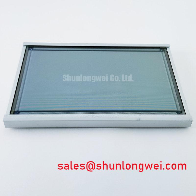
Check the disconnected panel’s identification label and connector orientation before attaching the display harness. Model: EL512.256-SG1 | Manufacturer: Planar | Display construction: Electroluminescent (EL) panel | Electrical ratings, timing and dimensions: Consult the model-specific datasheet.
I first compare the equipment schematic with the EL512.256-SG1 connector assignment, separating incoming power, image signals and chassis connections before investigating a missing image. This distinction matters because an electroluminescent panel is not an LCD with a separate backlight. Troubleshooting an LED string or replacing a backlight inverter does not address its light-generation mechanism. The initial repair question is whether the host delivers the correct power and image timing to the intended terminals.
Design Consideration: In AC electroluminescent displays, light generation depends on an alternating electric field across the emissive structure. Row and column drive waveforms jointly establish pixel excitation. Their timing relationship therefore matters alongside waveform amplitude: a synchronization error can disturb image formation even when the incoming supply appears stable. Inspect the host timing and accessible diagnostic signals against the equipment schematic rather than treating an illuminated background as proof that the complete signal path is healthy.
Push-pull drive stages and charge-recovery networks are circuit architectures to assess where the actual driver schematic identifies them, not features to infer from this part number. In a capacitive display load, energy transfer between switching stages and panel capacitance can affect supply current and waveform settling. A useful investigation compares the symptom with image content, refresh behavior and supply disturbance. Content-dependent instability can guide further measurements, but it does not by itself establish a failed resonant component or damaged panel dielectric.
Engineering Recommendation: Keep measurements at documented service points and use appropriately rated differential instrumentation when examining floating drive nodes. Probe loading and reference placement can alter the observed waveform. Evaluate pulse symmetry, settling and synchronization against the original circuit requirements; do not impose a generic excitation voltage, frequency or permissible DC offset on this model.
At the host interface, identify the actual signaling method before applying routing rules. LVDS differential-pair matching, TTL timing analysis and JEIDA/VESA mapping address different electrical or encoding questions; none establishes the EL512.256-SG1 pinout. For an interface conversion, compare connector assignments, logic thresholds, data order, synchronization polarity and startup behavior individually. A matching connector shell is not evidence of electrical compatibility.
Engineering Recommendation: If a replacement controller introduces an LVDS link, preserve differential-pair symmetry and verify receiver timing margin on the assembled harness rather than relying on nominal cable length alone. This is a system integration recommendation, not an assertion that the Planar panel accepts LVDS.
Servo-drive interference should be investigated by correlating image disturbance with equipment operating states. Inspect cable routing, shield termination and supply-return paths before attributing the symptom to the display. Controller communication also needs separate diagnosis: the Modbus protocol used with industrial programmable logic controllers concerns communication between devices, not the panel’s pixel interface. A stopped data update can leave a stable image on screen without indicating a display-drive failure.
When assessing a broader display-system redesign, TX18D203VM2BAA provides a separate product reference for comparison, not a backlight accessory for this EL panel. Any associated power conversion, illumination control or fault signaling belongs to that alternative system’s documented architecture. Keep those requirements separate from the Planar repair bill of materials.
Luminance Maintenance without Liquid Crystal Thermal Degradation
Record luminance under repeatable ambient lighting, image content and viewing geometry before deciding whether reduced readability originates in the panel or the front window. Surface contamination, reflections, supply behavior and drive conditions can influence the observation. Compare results with an established equipment baseline where available; visual impressions taken under different lighting conditions are weak evidence of emission degradation.
Design Consideration: Electroluminescent emission does not rely on liquid-crystal reorientation, so liquid-crystal freezing is not the appropriate explanation for its temperature-dependent behavior. That distinction does not establish a particular cold-start limit, response time or viewing-angle rating for the EL512.256-SG1. Temperature evaluation should examine the complete assembly, including controller startup, connectors, power conversion and optical window, against the equipment’s specified operating envelope.
Luminance half-life and mean time between failures describe different performance measures. A brightness-maintenance criterion tracks optical change under stated conditions; MTBF is a reliability metric dependent on its definition and assessment method. Neither can be converted into a guaranteed service interval for an individual panel. For maintenance planning, retain measured brightness, operating conditions and fault observations rather than assigning an unsupported lifetime figure.
For an enclosure integration, inspect mounting-hole alignment, bezel clearance and cable strain before tightening the assembly. Uneven support can transmit enclosure distortion into the display. If the assembly uses perimeter seals, inspect accessible edges for damage or contamination, but do not perform improvised pressure or immersion testing. A hermeticity test requires a specified method and acceptance criterion, while shock qualification requires evidence for the mounted assembly.
Front-window optics deserve a separate check. Compare readability under the intended illumination and viewing positions before adding an optical film. The principles of circular polarizers explain polarization behavior, but do not establish that this panel incorporates such a layer. Anti-glare treatments, anti-reflection coatings and added polarizers can change both reflected light and transmitted image brightness.
For potential AGV or forklift telematics integration, evaluate vibration exposure, enclosure reflections and operator viewing position as system requirements. If a touch overlay is added, assess glove and wet-surface operation using the selected touch controller and cover stack; those capabilities are not inherent EL-panel specifications. During replacement assessment, compare TX31D55VM2AAA only through a documented electrical, optical and mechanical compatibility review, not as an assumed interchangeable unit.
For troubleshooting across display technologies, The Ultimate Guide to Industrial TFT LCD Technology provides additional context for separating image-path, illumination and integration issues. On this EL assembly, close the service check by repeating the original image and lighting conditions after reassembly, confirming that the harness is unstressed and the bezel does not load the panel.