




Content last revised on October 23, 2026
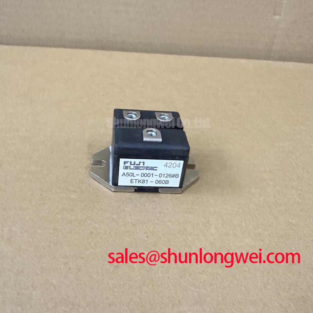
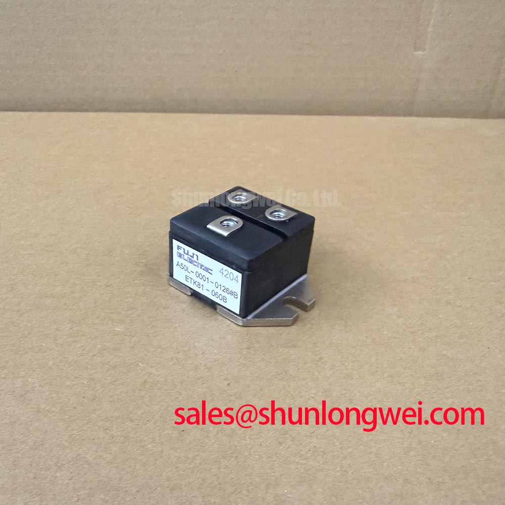
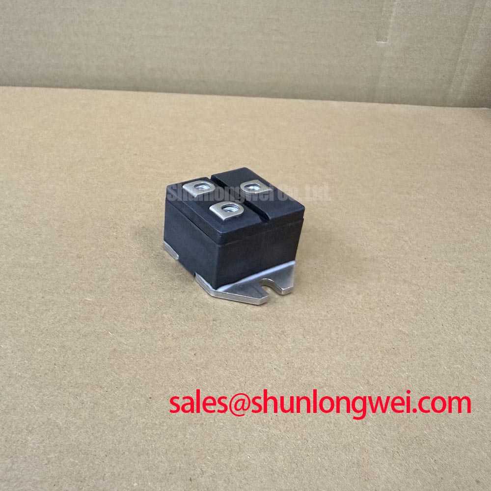
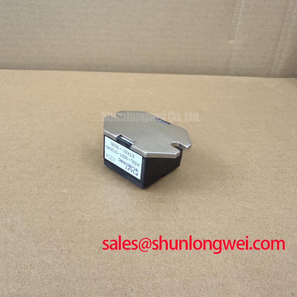
ETK81-060B Operational Boundaries: Evaluating Current-Limit Mode vs Linear Voltage Ramp Limits
- Confirm the cold-state terminal identification against the equipment wiring diagram before applying any test voltage.
- Record the diode-test response in both polarities and compare it with a known-good reference unit from the same circuit position.
- Inspect the mounting surface, thermal interface, terminal hardware, and insulation clearances before reassembly.
- Check the associated control and gate-drive wiring separately because a diode module does not provide a substitute for a thyristor gate circuit.
In a three-phase soft starter, the practical distinction between current-limit control and a linear voltage ramp is established by the controller, firing network, bypass arrangement, and protection coordination around the power module. The ETK81-060B should therefore be assessed as one part of the phase-power path rather than treated as an independent motor-current controller.
For a motor with locked-rotor demand several times above its running current, the commissioning engineer should confirm how the control system limits phase conduction and how the selected fuse responds to prospective fault current. A reduction target such as less than 2.5 times rated motor current is a system design objective, not a factory rating for this diode module. Confirm it through controlled current measurement on the complete starter, with the motor, bypass contactor, phase-angle controller, and protective devices installed in their intended configuration.
Fuse coordination must use the applicable Fuji protection data and the actual fuse I2t characteristic. Do not infer semiconductor survival from the fuse label alone. Terminal polarity, phase order, clamping surfaces, and insulation spacing should follow the original assembly layout. The standard industrial rating and standard operating current fields identify the product class, but the final voltage and current limits remain governed by the exact circuit, cooling method, duty cycle, and documented part data.
When comparing adjacent industrial component families, engineers may review the broader XILINX component category as a separate sourcing reference, without treating it as a direct electrical substitute for ETK81-060B.
ETK81-060B Operational Boundaries: Evaluating Gate Trigger Current Temperature-Dependent Limits
Gate-trigger current is not a defining test function for a diode module. It belongs to an associated thyristor or controlled rectifier stage, so a soft-starter repair should separate the ETK81-060B diode path from the firing board, pulse transformer, gate resistor, and control return. This distinction prevents an apparent firing fault from being assigned to the wrong power device.
Where the surrounding controller uses a fast gate pulse, a stated value such as greater than 1 A/µs must be treated as a system-driver target only when it appears in that controller’s design documentation. It is not an ETK81-060B factory specification. Temperature changes can alter semiconductor forward behavior, control-board timing, and heat-sink conditions, so the technician should compare phase conduction timing and device temperature under the same load conditions rather than rely on a single cold resistance reading.
Multi-pulse firing schemes, back-porch holding current, and pulse-train duration should be checked at the associated controlled device. The diode module should be checked for correct orientation, stable forward conduction, and absence of an unintended low-impedance path in the power circuit. A supply or gate-drive subsystem may also include a bootstrap capacitor and charging diode; its charging and discharge margin should be evaluated from the original control-board schematic. The related ZINC-MANGANESE-DRY-BATTERY category is a separate reference and must not be interpreted as the specified supply for this module.
🔧 Bench Diagnostic: Keep the device discharged and ESD-protected, then compare diode-test readings with a known-good cold reference before connecting the control harness.
Transient Dynamics & Electrical Design: Minimizing Commutation Turn-Off Voltage Spikes on ETK81-060B
Commutation stress in a soft starter is governed by circuit inductance, phase current, wiring geometry, snubber behavior, and the recovery characteristics of the installed semiconductor. The relevant reverse-recovery current and recovery time must be taken from the applicable Fuji documentation for the exact device configuration rather than estimated from package appearance or a handheld meter reading.
During switching evaluation, use an appropriately rated differential probe and current probe to observe the commutation event at the module terminals. Look for excessive voltage overshoot, ringing, uneven phase behavior, or a temperature rise that does not track the measured load current. These observations can indicate a layout, snubber, fuse, or control-timing issue, but they do not establish a single failed-part diagnosis without comparison against the known-good phase path.
Minimize stray commutation-loop inductance where practical, maintain short symmetrical power connections, and verify peak voltage margins against the system DC-link or line-voltage conditions during controlled testing. High-altitude operation, cosmic-ray exposure, and single-event reliability require system-level qualification data; they should not be presented as guaranteed limits for ETK81-060B without a documented source. Thermal interface condition and clamping uniformity also affect transient behavior, which is why the broader engineering discussion in The Advanced Thermal Management Revolution is relevant when reviewing the surrounding heat-removal structure.
For manufacturer background and related power-semiconductor families, consult Fuji Electric Power Semiconductor & IPM Modules. The complete assembly should be tested for insulation, phase balance, protection response, and thermal stability before returning a motor starter to service.