

Content last revised on September 19, 2026
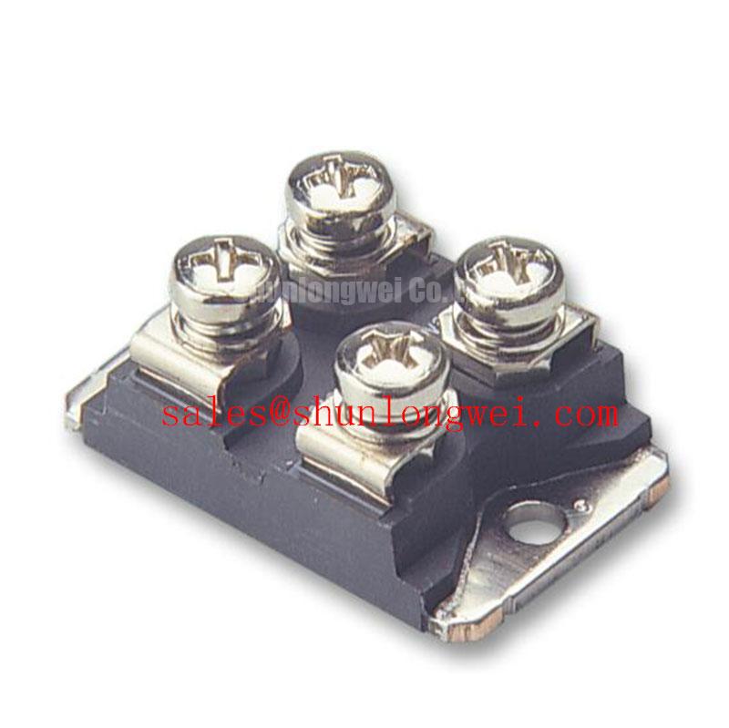
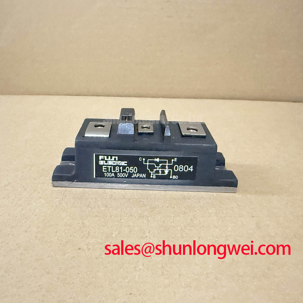
ETL81-050 Power Diode Bridge Module
Before reconnecting a failed rectifier stage, read the module marking against the service record and use a meter to check each accessible diode path for a consistent one way response after the DC link has been safely discharged. ETL81-050 is a Fuji Electric Power Diode Bridge Module rated at 2500 V and 80 A as an Official Datasheet Specification. Confirm the original bridge connection, terminal orientation, heatsink interface, and insulation arrangement before treating any replacement as electrically compatible.
| Parameter | Value | Classification |
|---|---|---|
| Manufacturer | Fuji Electric | Official product identification |
| Product model | ETL81-050 | Official product identification |
| Module type | Power Diode Bridge Module | Official product classification |
| Rated voltage | 2500 V | Official Datasheet Specification |
| Rated current | 80 A | Official Datasheet Specification |
ETL81-050 Circuit Protection & Reliability: Calibrating Sinusoidal 10ms Half Cycle Surge Current
The published identification data for the ETL81-050 establishes its 2500 V and 80 A ratings, but it does not establish an ITSM value, fuse I²t rating, or permitted repetitive surge profile. These figures must therefore be obtained from the applicable Fuji Electric documentation before a protection study is approved. Do not substitute a presumed surge current value from another bridge family.
During emergency maintenance, inspect the line side fuse condition, busbar discoloration, terminal hardware, and the flatness of the heatsink contact area. A diode bridge can show an abnormal cold test result after an upstream fault, but the meter alone does not reveal the fault energy that reached the module. Review the event sequence, check whether the AC input or DC output experienced a short circuit, and compare the fitted fuse characteristics with the original equipment documentation.
Fuse coordination is a Design Consideration: the protective device must interrupt fault energy within the limits established for the bridge and its conductors. The system engineer should verify the fuse I²t data, anticipated fault path, and the manufacturer’s semiconductor protection guidance rather than deriving suitability from the 80 A continuous rating alone.
⚠️ Field Alert: Tighten electrical and mounting hardware only to the equipment or module documentation requirements, because uneven force can impair contact quality or mechanically stress the module body.
Transient Dynamics & Electrical Design: Pulse Transformer Isolated Firing Circuit on ETL81-050
The ETL81-050 is identified as a power diode bridge module, not a gate controlled thyristor or IGBT assembly. It has no specified gate terminal, gate firing pulse requirement, holding current, pulse transformer interface, or multipulse firing scheme in the provided official data. Gate pulse rise time, back porch current, and gate hotspot analysis are therefore not applicable parameters for this particular diode bridge.
Where an induction melting or hardening furnace power supply contains separately controlled semiconductor stages, their isolated firing circuits must be evaluated against the documentation for those specific controlled devices. The bridge should be checked independently for correct AC input and DC output routing, adequate terminal contact, and voltage rating compatibility. A controller board fault and a rectifier bridge fault can coexist, yet they require separate evidence during diagnosis.
For a replacement evaluation, physical outline, terminal assignment, insulation arrangement, cooling method, and rectifier topology must match the original assembly. The 2DI100Z-140 can be reviewed as a separate power semiconductor listing, but its suitability must be determined from its own electrical, mechanical, and circuit documentation. It should not be assumed to be a direct replacement for the ETL81-050.
Transient Dynamics & Electrical Design: Junction to Heatsink Heat Dissipation in ETL81-050
No junction to case thermal resistance, case to heatsink resistance, mounting torque, or allowable junction temperature figure is included in the supplied official parameters for this model. Those values must not be inferred from the voltage rating, current rating, or appearance of the package. Obtain the relevant module data before calculating thermal margin or approving a changed cooling arrangement.
Heat transfer remains a Design Consideration during service work. Remove residue from the existing heatsink interface, inspect for burrs or corrosion, and check whether the mounting surface has been distorted by earlier tightening. Apply thermal interface material according to the original equipment procedure and tighten mounting points progressively in the stated sequence. The objective is uniform contact pressure without bending the module or leaving dry areas in the thermal interface.
On a furnace rectifier, thermal evidence should be reviewed alongside electrical evidence. Repeated overheating can be associated with restricted airflow, impaired liquid cooling, loose high current connections, abnormal line conditions, or an overloaded downstream DC stage. Measure the actual operating conditions and compare them with the machine documentation before assigning one cause. The 80 A rating is an Official Datasheet Specification, not a complete thermal operating limit for every enclosure and duty cycle.
Field Diagnostics & Commissioning: RC Snubber Network Optimization in ETL81-050 Topologies
An RC snubber network can limit ringing where circuit inductance and switching events produce transient stress, but its resistor and capacitor values are system determined. For the ETL81-050, no snubber component values are supplied as Official Datasheet Specifications. Designers should characterize the actual waveform, DC bus conditions, wiring geometry, and temperature during controlled commissioning before validating any network change.
Keep high current conductors short and mechanically secure where practical to reduce parasitic loop inductance and associated transient voltage excursions. After installing the bridge, verify conductor clearance, polarity, terminal torque records, and the waveform at relevant system test points. A recurring fuse operation or unstable DC output may indicate more than one issue, so check the bridge, snubber parts, busbar joints, sensing circuit, and downstream load without assuming a single failure mechanism.
For EMC context, the system level nature of conducted and radiated interference is outlined in Electromagnetic Compatibility in Power Electronics. Current feedback hardware should also be assessed when protection behavior appears inconsistent; Giant Magnetoresistance and TMR Sensors for Industrial Current Measurement provides background on a sensing principle used in industrial measurement systems.
If a furnace service panel or monitoring display is also being investigated during commissioning, interface and panel level checks should remain separate from the power bridge assessment. The Ultimate Guide to Industrial TFT LCD Technology provides relevant reference material for industrial display diagnostics.