

Content last revised on September 20, 2026
Preventing Spurious Faults: Kelvin Emitter Connection Guidelines for EVK31-050
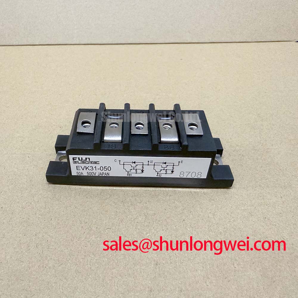
Before reconnecting a removed module, isolate the converter, inspect the terminal faces and mounting base, and verify that the nameplate identification matches EVK31-050, rated at 2500V and 50A as listed specifications. This Fuji Electric Power Module must be evaluated against the original equipment schematic before any wiring change, particularly where a gate driver uses a separate emitter sense return.
Design Consideration: when the original circuit provides an auxiliary emitter return, it should be routed separately from the main high current emitter path until it reaches the driver reference point. This reduces shared inductive voltage in the gate loop during switching. A shared return can introduce gate reference movement that may appear as unexplained driver trips, irregular switching waveforms, or intermittent protection events.
During repair, compare the removed assembly with the original wiring diagram rather than assuming that every terminal serves the same function across module families. Keep the gate loop compact, protect low level driver conductors from busbar movement, and inspect for loose control connectors or damaged insulation near power terminals. If waveform evidence suggests ringing, verify the gate to emitter measurement directly at the module connection and compare it with a known stable phase leg.
⚠️ Maintenance Note: Periodically monitor terminal contact temperature and confirm that cooling airflow paths remain clear before returning the converter to sustained load.
For driver turn off behavior, the engineering reference Evolution of Negative Off Bias Gate Drive Circuits can help system engineers assess the general role of gate reference control; the required drive conditions for EVK31-050 must still be verified from the original equipment documentation.
Preventing Spurious Faults: DC Bus Low Inductance Laminated Busbar Guidelines for EVK31-050
Verify terminal identification and busbar orientation before tightening the DC link assembly around the EVK31-050. The official voltage rating is 2500V, but the actual switching peak in an installed converter depends on DC link voltage, commutation current, loop inductance, and switching rate. Engineering Calculation expresses this relationship as the DC link voltage plus the product of stray inductance and current change rate. That is why busbar geometry, capacitor proximity, and physical fastening affect measured voltage stress.
Design Consideration: use a compact, symmetric current loop between the DC link capacitor, module terminals, and return path to reduce parasitic inductance and suppress turn off overshoot. A laminated busbar arrangement can support this objective when its conductor spacing, insulation system, creepage distances, clearances, and hardware are verified for the complete cabinet environment. The final acceptable peak margin must be established by system switching tests against the actual DC link voltage.
Inspect busbar flatness, terminal seating, and fastener retention after transport vibration or repeated thermal cycling. Uneven pressure or a shifted busbar can increase contact resistance and create localized heating. Snubber capacitor selection and placement are system determined and should be validated with measured switching waveforms, not selected solely from a module current rating.
Where the same equipment includes an upstream rectifier or related power stage, the separate 6MBI300U-120 listing may be useful for parts documentation. Its electrical suitability must be checked independently against the relevant circuit and original design records. For product family context, consult the Fuji Electric Power Semiconductors Portal.
Transient Dynamics & Electrical Design: High Speed Fault Management for EVK31-050
Fault protection should be checked as a complete driver and power loop, not inferred from the module label. The EVK31-050 carries official ratings of 2500V and 50A, while desaturation sensing, short circuit response, and soft turn off behavior belong to the surrounding gate driver implementation unless specified in the original converter documentation.
Engineering Recommendation: review the measured collector to emitter voltage, gate command, DC bus voltage, and fault flag on the same time base during controlled commissioning. A rising collector to emitter voltage while the gate command remains asserted may require investigation of load conditions, driver supply integrity, gate path continuity, or a developing power loop issue. It does not establish a single cause without waveform comparison.
Where a driver uses staged turn off after a fault, its gate resistance network and timing should be retained or validated as part of the equipment design. The aim is to remove fault current without generating excessive inductive voltage in the commutation loop. Engineers should verify protection timing and switching peaks under representative operating conditions while respecting the equipment manufacturer’s safe operating requirements.
For commercial string inverter and microgrid energy storage service, phase controlled front ends and inverter bridges can also produce system level current distortion if control timing or line filtering is disturbed. Harmonic performance is an equipment level result, so it should be assessed with the complete grid interface rather than attributed to this individual module. Fuji Electric’s Power Integrated Module information provides useful context on integrated power semiconductor categories.
EVK31-050 Thermal Electrical Optimization: Four Quadrant Power Flow Topologies for Practical Tuning
Clean the heatsink fins, inspect fan operation, and examine the thermal interface condition before attributing overtemperature alarms to the EVK31-050. The module is specified as a Fuji Electric Power Module with 2500V voltage capability and 50A current capability. No thermal resistance, junction temperature, switching loss, or mounting torque value is stated here, so those limits must be taken from the original module documentation and converter service data.
In four quadrant battery and inverter link operation, current direction and loading can change repeatedly during charge, discharge, and peak shaving events. Design Consideration: evaluate thermal cycling through measured case temperature, heatsink condition, airflow stability, and operating waveform data. Repeated temperature variation may point to cooling degradation, uneven thermal contact, or changing load duty, but each possibility requires inspection and measurement.
Before fitting a replacement module, compare terminal arrangement, control interface, mechanical mounting arrangement, and electrical ratings with the removed unit and equipment bill of materials. The 3MBI50SX-120-02 can be reviewed as a separate listed device during material cross reference work, but it should not be treated as an automatic substitute for EVK31-050. System integrators should verify all electrical, mechanical, thermal, and driver compatibility conditions before installation.