

Content last revised on September 23, 2026
FF200R12MT4 Overview
Before fitting FF200R12MT4, isolate the DC link, inspect the module terminals and housing for heat marks or mechanical stress, then compare the installed inverter nameplate requirements against its 1200 V voltage rating and 200 A current rating.
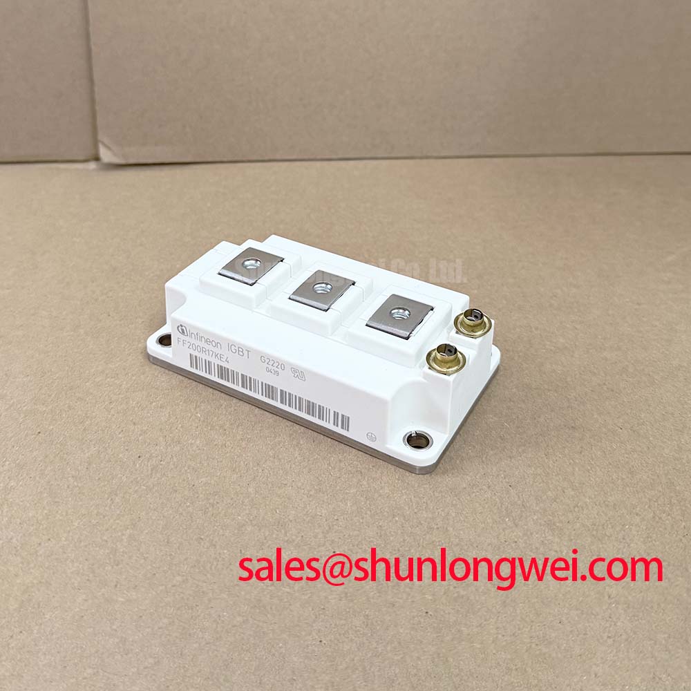
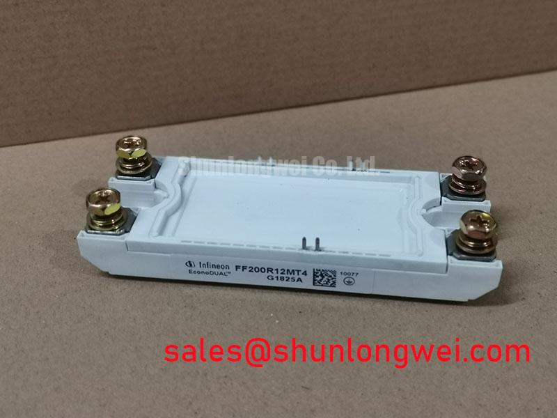
The Infineon FF200R12MT4 is an IGBT power module supplied in a Module package. Its stated electrical identity is 1200 V and 200 A, identified here as Official Datasheet Specifications. For a repair or replacement evaluation, those ratings are only the first checkpoint. The original converter topology, gate driver arrangement, cooling interface, DC link voltage, switching conditions, and protection settings must also be verified before energizing the equipment.
| Parameter | Specification | Classification |
|---|---|---|
| Model | FF200R12MT4 | Official product identification |
| Manufacturer | Infineon | Official manufacturer identification |
| Rated voltage | 1200 V | Official Datasheet Specification |
| Rated current | 200 A | Official Datasheet Specification |
| Package | Module | Official package classification |
For broader device-family context, the Infineon IGBT Modules and Discretes portfolio and the manufacturer’s IGBT modules overview provide useful reference material when confirming driver and inverter documentation.
FF200R12MT4 Circuit Protection & Reliability: Calibrating Desaturation Detection
During an inverter failure investigation, check whether the driver recorded a desaturation trip, overcurrent fault, gate supply loss, or controller shutdown event before replacing the power module. A damaged IGBT module can be the consequence of a protection failure rather than the original fault source. Cold resistance checks between power terminals can identify obvious low impedance faults, but they cannot prove switching integrity or confirm the condition of the gate drive circuit.
Desaturation monitoring is a Design Consideration for an IGBT inverter using FF200R12MT4. The driver monitors the collector to emitter voltage during commanded conduction. If the voltage rises abnormally while gate drive remains active, the protection circuit can interpret that condition as a possible overload, short circuit, or abnormal commutation event. The detection threshold, blanking interval, sensing network, and driver response time must be verified against the original inverter documentation and the applicable device characteristics.
A practical protection sequence should avoid an uncontrolled hard interruption when substantial current is present. Two stage soft turn off is commonly considered where the driver first reduces gate drive in a controlled manner, then completes shutdown after the current transient is managed. This is an Engineering Recommendation rather than an official module setting. The required behavior depends on DC link energy, commutation inductance, motor load conditions, and the converter’s measured voltage margin during switching tests.
When a drive repeatedly trips during acceleration, lift motion, or regenerative braking, inspect the desaturation diode path, gate driver supply rails, driver isolation barrier, and gate return routing. A noisy sensing path may create false trips, while an ineffective protection path may allow excessive fault energy. Compare the waveform with a known healthy phase where available, using appropriate isolated measurement equipment.
Assembly Integrity & Layout Architecture: Preventing High dv/dt Cross Conduction Shoot Through for FF200R12MT4
Cross conduction should be treated as an inverter assembly and gate drive problem, not as a module characteristic alone. In a bridge leg, rapid collector voltage movement can couple through parasitic capacitances and induce an unwanted gate voltage rise in the complementary switch. If that switch partially turns on while its partner is conducting, DC link current can rise sharply and protection may respond too late to prevent damage.
A dedicated active Miller clamp and an appropriately controlled negative gate bias are common Design Considerations for suppressing unintended gate turn on. The actual gate voltage range, clamp behavior, resistor selection, and driver supply arrangement are determined by the installed gate driver and must be validated on the finished power stage. Do not copy values from a different inverter merely because it uses the same voltage class.
Keep the commutation path physically compact and maintain a low impedance gate return path to reduce turn off overshoot and unwanted gate coupling. Laminated bus structures, close DC link film capacitor placement, and symmetrical conductor geometry are often evaluated by power stage designers. Their effectiveness should be confirmed by observing collector emitter voltage and gate emitter voltage at realistic current and temperature conditions.
Field Alert: Disconnect and verify the DC link is discharged before touching gate or power connections, because reconnecting a gate lead with stored bus energy can create an uncontrolled switching event.
Mechanical assembly also deserves close attention. Confirm that mounting surfaces are clean, planar, and free from trapped debris. Thermal interface material should be applied as a uniform thin layer according to the system’s approved maintenance process. Fastener torque must follow the equipment manufacturer’s mechanical documentation and the specified screw hardware, rather than an assumed generic value. Uneven clamping can affect thermal contact and may introduce stress into the module housing.
For applications where engineers are reviewing a substantially different power-module format or current class, the FZ3600R12HP4 can be reviewed as a separate technical reference. Electrical topology, mounting arrangement, gate driver compatibility, cooling requirements, and protection coordination must be assessed independently before any replacement decision.
Field Diagnostics & Commissioning: Multi Module Parallel Current Sharing in FF200R12MT4 Topologies
Parallel module arrangements require evidence from the actual inverter rather than an assumption that identical labels guarantee equal current sharing. Begin commissioning with the power stage disconnected from the load where safe procedures allow, then verify polarity, terminal fastening, gate wiring continuity, driver enable logic, and current sensor feedback. Once low energy functional checks pass, examine phase current and gate waveforms during controlled operation.
IGBT devices can exhibit a positive temperature coefficient in the relevant operating region, which can assist steady state current sharing under suitable conditions. That behavior does not eliminate the need for matched electrical paths. Dynamic sharing is strongly influenced by gate loop resistance, gate return inductance, driver timing, DC bus geometry, thermal contact, and measurement accuracy. A module that receives a faster gate command can carry disproportionate transient current even if the static current later appears balanced.
As a Design Consideration, use symmetrical physical routing for parallel gate loops and comparable connections from the DC link to each module position. System engineers should verify current balance with properly rated probes and compare waveforms across the parallel positions. A difference may indicate unequal path impedance, driver timing variation, a degraded gate component, or a measurement reference problem. It should not be diagnosed from one waveform feature alone.
For electric material handling and forklift traction inverter repairs, confirm the operating mode that preceded the fault. High torque launch, repeated reversing, lift hydraulic demand, and regenerative events can expose different sections of the inverter control strategy. Check whether the fault appears on only one phase, only under motion, or during DC bus transitions. This helps separate a power-stage concern from feedback, motor cable, contactor, battery, or control-command issues.
Where current sharing appears unstable, inspect the cooling path as carefully as the gate path. Differences in heatsink contact, airflow, liquid cooling flow, or thermal interface condition can shift device temperature and influence operating behavior. These are system-level checks and do not represent a lifetime prediction or guaranteed thermal capability for the module.
FF200R12MT4 Thermal Electrical Optimization: Suppression of 2x VDC Voltage Doubling at Practical Tuning
Long motor cables can behave as transmission lines during fast inverter switching. A voltage wave launched from the inverter can reflect at the motor end when cable and motor impedances differ. Under unfavorable conditions, the reflected waveform can raise terminal voltage substantially above the DC link level, sometimes approaching a doubling effect. The actual peak depends on cable construction, cable length, motor impedance, switching edge behavior, grounding arrangement, and filter placement.
For a 1200 V IGBT module installation, verify measured collector emitter peaks against the inverter’s approved voltage limits during representative switching tests. The module’s 1200 V rating is an Official Datasheet Specification, but it is not a substitute for confirming real transient voltage at the installed power terminals. Probe connection quality matters because excessive probe loop area can create misleading high frequency ringing.
Output dv/dt filters, sine filters, common mode chokes, and motor-side protection measures are system-level options that may be evaluated when cable reflections or insulation stress are observed. Their selection must consider motor type, cable routing, switching frequency, allowable voltage drop, control stability, and thermal loading. The system integrator should validate any filter arrangement under the equipment’s actual duty cycle rather than treating a generic filter as a guaranteed cure.
Inspect DC link capacitor connections and busbar joints when overshoot is present at the module. Loose hardware, elongated current paths, or separated capacitor placement can increase inductive voltage during current commutation. Minimizing parasitic loop inductance is an Engineering Recommendation intended to suppress turn off overshoot, with the final layout verified by measured switching waveforms and peak margins against the operating DC link voltage.
For engineers comparing inverter switching approaches and power-stage behavior in three-phase conversion, The 1200 V CoolSiC™ MOSFET Advantage in Three provides related technical context. Any change from an IGBT module to another semiconductor technology requires a full review of driver behavior, control timing, cooling, transient voltage, and protection coordination.