

Content last revised on October 26, 2026
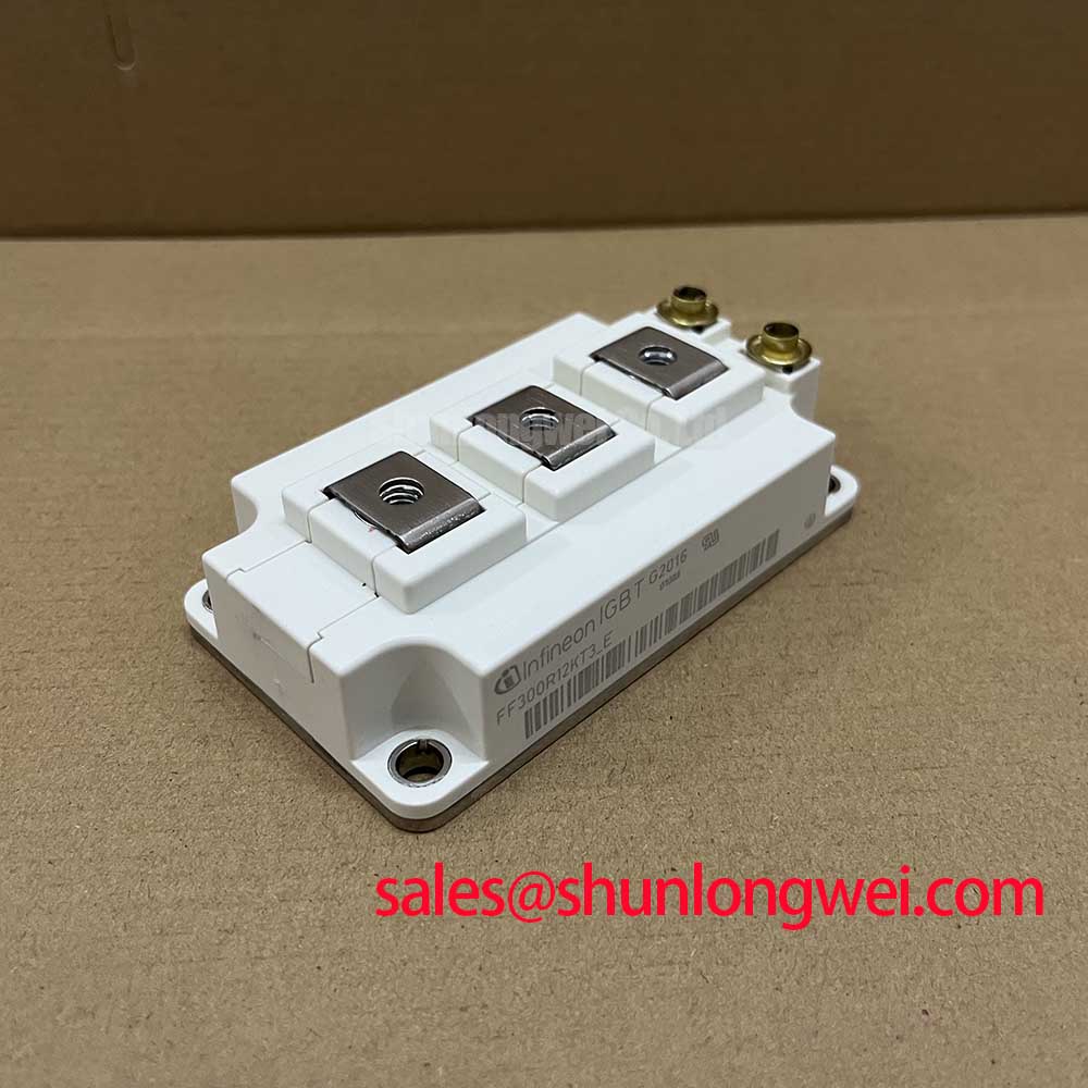
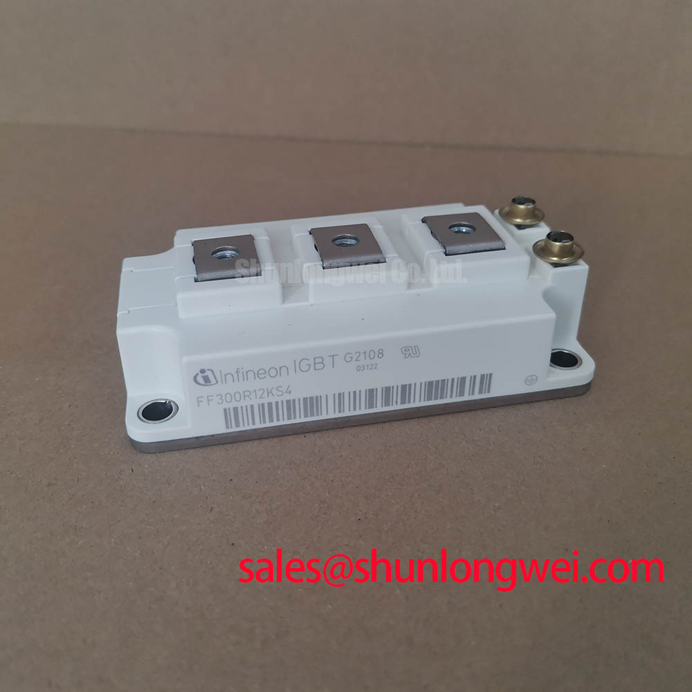
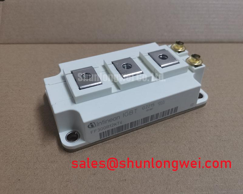
Preventing Spurious Faults: Motor-Terminal Voltage Doubling Guidelines for FF300R12KT4
I first separate a suspected module fault from a cable reflection problem by comparing the switching waveform at the inverter output with the waveform at the motor terminals. As a Design Consideration, an impedance discontinuity between a long cable and its motor can reflect a traveling voltage wave, allowing the motor-terminal excursion to approach twice the incident voltage step under idealized conditions. This is not a guaranteed doubling of the voltage across the FF300R12KT4.
For incoming inspection, identify collector, emitter, and gate connections from the terminal drawing rather than connector position alone. With the module disconnected and safely discharged, diode-mode measurements across documented diode paths provide a cold-state comparison. Record instrument polarity, module temperature, and whether parallel circuit paths remain connected. A difference from a known-good reference warrants investigation; a handheld reading does not establish blocking-voltage capability or switching performance.
💡 Bench Tip: Keep the gate under ESD protection and compare cold-state readings with a known-good reference using the same meter and lead polarity.
During powered investigation, use appropriately rated differential probes and distinguish motor-terminal reflections from local collector-emitter overshoot. A dv/dt filter or output choke should be evaluated against cable characteristics, motor insulation requirements, switching conditions, and its own thermal loading. Keep the local commutation loop compact to reduce turn-off overshoot; determine conductor spacing from the equipment insulation requirements rather than an arbitrary layout rule.
When assessing compatibility with a heavy-duty variable-frequency AC motor drive, compare the FF300R12ME4_B11 as a reference candidate, not an automatic replacement. Terminal geometry, mounting interfaces, gate-drive requirements, and switching characteristics require comparison alongside headline ratings.
Transient Dynamics & Electrical Design: Sizing Braking Resistors and Chopper Transistors for FF300R12KT4
Trace the regenerative current path on the equipment schematic before attributing deceleration overvoltage to the FF300R12KT4. As a Design Consideration, a braking chopper controls energy transfer from the DC link into a braking resistor; the module’s 1200 V and 300 A ratings do not establish the equipment’s braking capacity or confirm an integrated braking function.
Resistor assessment starts with the driven load’s inertia, speed change, externally applied load, and repetition pattern. The engineer should translate that operating cycle into pulse-energy and average-dissipation requirements, then compare both against the resistor manufacturer’s ratings. Resistance also affects chopper current, so an energy-capable resistor can still impose an unacceptable semiconductor load. Check enclosure ventilation and thermal protection along with resistance measured at a documented temperature.
For the chopper switch, evaluate blocking stress, pulse current, switching losses, and the applicable safe operating area at the expected temperature. Investigate the DC-link waveform through the deceleration interval, not just its highest recorded point. A rising bus voltage can involve chopper command timing, resistor continuity, feedback behavior, or operating conditions; the waveform and schematic should guide isolation of the cause.
High-speed fuse coordination requires the selected fuse’s clearing behavior at the actual circuit voltage and prospective fault current. Its I²t characteristic must not be treated as a universal IGBT survival criterion. Fast electronic detection and controlled shutdown address semiconductor fault stress, while the fuse serves its coordinated circuit-protection role. For desaturation protection, evaluate detection blanking, collector-emitter sensing, and soft turn-off against the device’s documented short-circuit conditions rather than deriving a trip threshold from a typical saturation-voltage value.
Preventing Spurious Faults: Dynamic Power Loss Dissipation and Multi-RC Guidelines for FF300R12KT4
Reconstruct the overload pulse and its preceding thermal history before interpreting a case-temperature measurement as evidence of adequate junction margin. As a Design Consideration, the junction responds to changing semiconductor losses faster than an externally mounted temperature sensor can necessarily report. Brief overloads therefore require transient thermal analysis rather than an average-power calculation alone.
An Engineering Calculation can estimate the junction-temperature rise for a suitable rectangular loss pulse by multiplying pulse dissipation by the manufacturer’s junction-to-case transient thermal impedance at that pulse duration. Repetitive or irregular loading needs a time-dependent treatment that includes earlier pulses. Use the device-specific thermal curve or a corresponding fitted multi-RC model, retaining its stated boundary conditions; thermal coefficients from another module are not interchangeable.
Loss inputs should reflect conduction current, duty cycle, junction temperature, and switching conditions. Switching-energy data must be interpreted at their stated test conditions before being applied to an operating waveform. Manufacturer terminology and product resources are available through the Infineon IGBT Modules & Discretes Official Portfolio. Validate the resulting temperature estimate against measured case behavior and the cooling assembly’s operating state.
Inspect mounting-surface condition, flatness, thermal-interface coverage, and fastening sequence when calculated and observed temperatures disagree. Apply interface thickness and mounting torque from the applicable assembly instructions; neither is a generic consequence of the electrical ratings. Do not apply press-pack spring-pressure procedures or assume double-sided cooling for this module. For broader topology context, Peak Efficiency in Solar and Energy Storage provides a separate discussion; topology-level efficiency does not establish this component’s service life.
Transient Dynamics & Electrical Design: Optocoupler vs Digital Coreless-Transformer Drivers for FF300R12KT4
Compare the gate command at the driver input with the gate-emitter waveform during switching transitions to investigate unintended pulses. As a Design Consideration, optocoupler and coreless-transformer driver technologies must be evaluated through their individual specifications, not ranked by isolation method alone. Propagation behavior, output-stage capability, supply behavior, and common-mode transient immunity all affect integration.
Separate the driver’s isolation barrier from the module’s insulation requirements. A dielectric withstand test value does not independently establish reinforced insulation, allowable continuous working voltage, or the equipment’s required clearance. Review the applicable insulation documentation, board geometry, and environmental conditions before selecting a driver. Repeated high-voltage testing also needs an approved procedure; it is not a substitute for incoming terminal checks.
Common-mode transient immunity should be assessed under the driver manufacturer’s stated test conditions and compared with measured switching-node slew behavior. Keep gate-drive return paths controlled, separate sensitive detection wiring from power commutation paths, and inspect local driver-supply decoupling. Establish routing and spacing through the system’s electrical and insulation requirements rather than imposing an unsupported universal dimension.
When a suspicious gate pulse appears, compare measurements using a suitable probe arrangement before changing the driver. Probe coupling, supply disturbance, Miller coupling, and protection activity can produce different signatures. Capture gate voltage, collector-emitter voltage, and the protection command together so the event sequence remains visible. Any adjustment to gate damping or soft shutdown should then be checked for both unintended turn-on and increased turn-off stress under the equipment’s relevant operating conditions.