
Content last revised on September 10, 2026
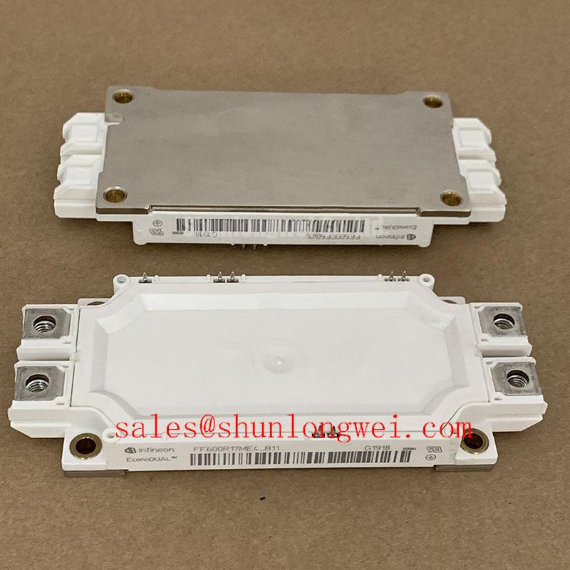
Optimizing Thermal Performance: Infineon FF600R07ME4_B11 650V 600A IGBT Module
Solderless connection reliability meets advanced trench technology for high-density, low-voltage power converters.
Top Specs: 650 V | 600 A | Ptot 1800 W
- Reduces thermal path resistance.
- Eliminates solder fatigue defects.
How does the solderless connection maintain reliability under harsh vibration? The mechanical PressFIT design creates a gas-tight contact, ensuring continuous connection.
Application Scenarios & Value
Optimizing Performance in Solder-Free Power Converters
For low-voltage solar inverters prioritizing solderless reliability, this 650 V module is the optimal choice. Engineers often face the challenge of design failure under harsh physical vibration. In industrial environments, traditional solder joints can fatigue over time. The FF600R07ME4_B11 addresses this vulnerability by utilizing a PressFIT contact technology.
For instance, when managing motor startup inrush currents in commercial agriculture vehicles, thermal cycling can stress conventional connections. Because this module features a 600 A continuous collector current and 1200 A peak current rating, it handles extreme transient peaks safely. The EconoDUAL™3 housing design keeps parasitic inductance minimal. This reduces voltage spikes and safeguards the switching stage.
While the FF600R07ME4_B11 is tailored for 650V low-voltage applications, systems demanding higher voltage ratings can utilize the related FF600R12ME4 to handle up to 1200V.
Technical Deep Dive
Analyzing the PressFIT Assembly and Thermal Control Mechanics
The Trench/Fieldstop IGBT4 technology inside this Infineon IGBT Module optimizes carrier distribution to reduce collector-emitter saturation voltage (VCE(sat)). A lower VCE(sat) directly correlates to minimized conduction losses during steady-state operation.
Think of VCE(sat) as the friction of a water valve. The lower the friction, the less energy is wasted as heat when water flows through. In this power stage, lower conduction losses mean less heat generated at a full load of 600 A.
Similarly, the thermal resistance (Rth(j-c)) acts like a thermal highway. The copper base plate provides a wide, fast lane for heat to escape from the silicon die to the external heatsink. This allows the module to sustain a total power dissipation (Ptot) of 1800 W safely.
The solderless PressFIT assembly creates a cold-welded, gas-tight mechanical bond. This eliminates the voiding issues common in liquid soldering, delivering high power cycling capability. These structural design considerations are key when engineering robust gate drivers. Implementing a reliable drive circuit prevents catastrophic failures, which we analyze in our guide on IGBT gate drive design.
For a wider context on industrial power stages, engineering teams can consult the engineer's guide to IGBT modules.
Key Parameter Overview
Essential Specifications for Advanced System Integration
For comprehensive electric performance curves and mounting guidelines, download the FF600R07ME4_B11 datasheet.
| Parameter | Symbol | Rating / Value | Engineering Relevance |
|---|---|---|---|
| Collector-Emitter Voltage | VCES | 650 V | Optimized for low-voltage power stages and battery setups. |
| Continuous DC Collector Current | IC nom | 600 A | Enables high power density within compact cabinets. |
| Repetitive Peak Collector Current | ICRM | 1200 A | Handles transient startup current surges. |
| Total Power Dissipation | Ptot | 1800 W | Absolute limit at TC=25°C under optimal heat dissipation. |
| Gate-Emitter Peak Voltage | VGES | ±20 V | Standard control voltage range for industrial driver systems. |
| Isolation Voltage | Visol | 4000 V (AC, 1 min) | Provides strong electrical isolation between logic and power. |
Frequently Asked Questions
Technical Clarifications on Operation and Reliability
What are the core advantages of the PressFIT contacts on the FF600R07ME4_B11?
PressFIT pins create a gas-tight mechanical joint with the PCB, avoiding cold joints or voiding found in soldering. This improves thermal cycles and mechanical connection reliability by avoiding solder fatigue under physical stress.
Can you run this module at junction temperatures above 150°C?
The continuous operating junction temperature is rated up to 150°C (Tvj op). Peak overload temperatures up to 175°C are permissible briefly, but staying within 150°C is best practice for long-term reliability.
Is there an integrated temperature sensor in this module?
Yes, an integrated NTC thermistor is included, simplifying system thermal monitoring and facilitating over-temperature protection without needing external discrete sensors.
How should a technician check the health of this module?
To run general diagnostics, refer to our field guide on testing an IGBT module with a multimeter to check the gate-emitter and collector-emitter junctions.
By matching advanced IGBT4 chip design with a robust EconoDUAL™3 package, the FF600R07ME4_B11 offers a balanced solution for modern, high-density power stages. Deciding whether to utilize this solderless architecture enables system designers to lower manufacturing defect rates and maintain robust performance across long operational lifespans.