

Content last revised on September 10, 2026
Industrial Bezel Mechanical Envelope Tolerances and Mounting Screw Torque Optimization
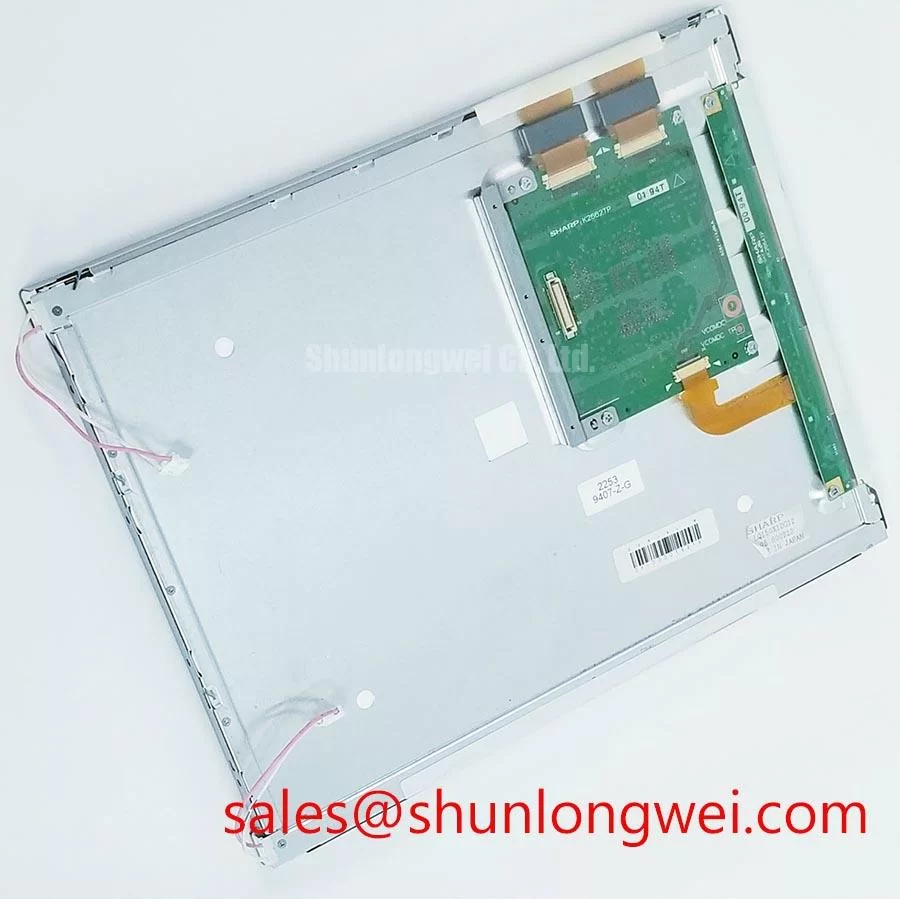
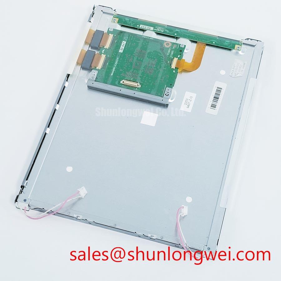
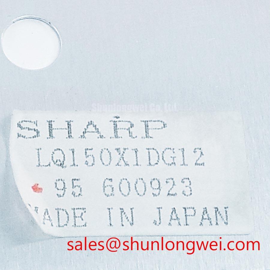
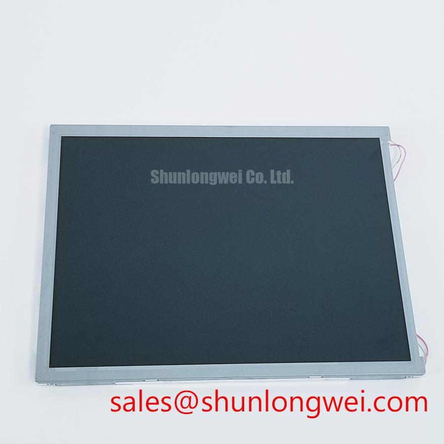
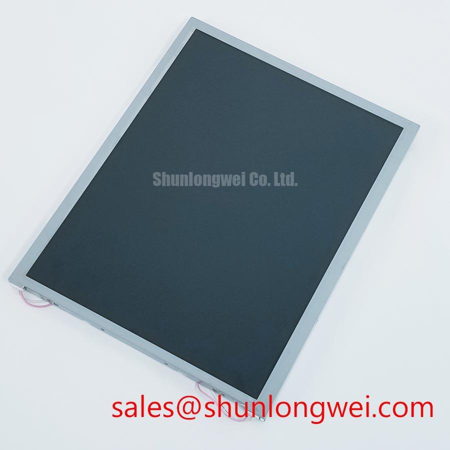
Disconnect the display assembly, inspect the bezel and FFC or LVDS connection for mechanical stress, and compare the installed label with LQ150X1DG12 before applying power. This Sharp unit is identified as an Industrial Grade LCD/HMI Panel with a TFT-LCD Display Module construction. The supplied factory information does not confirm resolution, interface pinout, supply voltage, backlight type, viewing angle, optical bonding, or environmental ratings, so those values must be checked against the original Sharp documentation and the equipment service record before replacement.
| Model | LQ150X1DG12 |
| Manufacturer | Sharp |
| Product category | Industrial Grade LCD/HMI Panel |
| Module construction | TFT-LCD Display Module |
| Specification status | Model identity supplied; detailed parameters require verification |
For repair purchasing, the model number is the primary identity reference. A visually similar 15-inch panel can still differ in connector assignment, timing requirements, backlight drive arrangement, mounting-hole position, or controller compatibility. The system integrator should verify the required supply voltage from the original panel documentation rather than selecting a value from a general LCD family assumption. The same verification applies to the signal interface, power sequencing, backlight enable logic, and display timing.
Start the mechanical inspection with the failed display removed from the equipment. Check whether the metal bezel, mounting frame, or rear support has been distorted before transferring the replacement module. A frame that is twisted can impose uneven pressure on the display assembly and create localized optical non-uniformity, intermittent connection faults, or stress around the panel edge. These symptoms should be assessed as possible results of combined mechanical and electrical conditions rather than assigned to one cause without testing.
The factory information supplied for LQ150X1DG12 does not provide the outer bezel dimensions, mounting-hole coordinates, panel depth, or approved fastener torque. Those values should be taken from the original mechanical drawing or measured from the equipment chassis. The opening should be checked at several points instead of relying on one diagonal measurement. Confirm that the module seats without forcing the frame, that the connector area remains free from contact with sheet metal, and that the cable bend does not pull against the panel socket.
As a Design Consideration, fasteners should be tightened progressively in a cross pattern so that the bezel does not draw down on one side first. Any torque value used in production must come from the Sharp mechanical specification or the equipment manufacturer’s assembly procedure. A generic fastener torque is not an official parameter for this model. Where the original unit uses an elastomer gasket, spacer, or floating bracket, preserve the original stack-up and do not replace it with a rigid clamp without validating the optical and mechanical result.
Display timing also needs to be separated from the physical installation check. TTL or LVDS transmitter clock stability, data hold time, pair routing, and controller timing are system-level matters unless the panel documentation explicitly specifies them. When a replacement powers up with unstable characters, intermittent lines, or a blank image, compare the signal at the panel connector with a known-good assembly. Inspect connector seating, ground continuity, enable sequencing, and the controller configuration before changing timing values.
LMS700KF01-001 may be reviewed as a separate same-class panel reference during cross-model evaluation, but compatibility must be established from documented dimensions, interface details, timing, and electrical requirements. Similar screen size alone is not sufficient evidence for a direct substitution.
Surface Anti-Glare and Anti-Reflective Coating for High Ambient Readability
Readability complaints should be investigated at the installed equipment rather than judged from a loose panel on a workbench. Record the viewing position, surrounding light sources, protective window condition, and image content shown by the HMI. Reflections from a cab window, overhead lighting, or a cover lens can be mistaken for a panel contrast problem. Clean the external optical surfaces with the procedure approved for the equipment, then compare the image with the original display under the same lighting direction.
The supplied factory data does not confirm whether LQ150X1DG12 uses an anti-glare surface, an anti-reflective treatment, a particular liquid-crystal mode, or a specified viewing-angle performance. Do not assign an IPS, MVA, or TN optical characteristic to this model without the applicable datasheet. Likewise, a symmetric viewing cone such as 85 degrees in each direction must not be presented as a factory value unless it appears in the original Sharp specification.
For a railway passenger information system or cab signalling display, designers should evaluate the panel together with the front cover, bezel depth, ambient illumination, and operator viewing position. A matte surface can reduce mirror-like reflections but may alter perceived image sharpness. A clear cover can preserve apparent detail while increasing reflected light. The correct choice is determined by the complete optical stack and the display content, not by the LCD module name alone.
Cold-environment diagnosis requires controlled observation. Liquid-crystal response can change with temperature, and a slow image transition may also involve the controller, power rail behavior, backlight control, or software refresh conditions. The supplied information gives no operating-temperature range, response-time specification, heater provision, or control method for this model. The integrator should therefore verify the environmental rating and any cold-start procedure from the original panel documentation before adding heating hardware or modifying the power sequence.
Check grayscale transitions, fine text, warning symbols, and large uniform fields after the panel has reached the equipment’s normal operating condition. A color or contrast shift that changes with viewing angle may be optical; a fixed vertical or horizontal artifact should also prompt inspection of the cable, connector, controller output, and chassis grounding. The diagnostic objective is to compare repeatable observations against the known-good signal path, not to infer a specific internal failure from one visual symptom.
Aluminum Heat Spreader Sizing and Thermal Interface Placement along Narrow Display Edges
Before adding any heat spreader, map the temperature distribution around the installed display using the equipment’s approved thermal inspection method. Pay attention to the bezel edges, backlight driver area, cable exit, and nearby power components. A warm region beside the module may originate in the display, the enclosure, a converter, or an adjacent drive circuit. The LQ150X1DG12 factory information supplied here does not specify LED backlight power, allowable surface temperature, heat-spreader dimensions, thermal resistance, or lifetime data.
Aluminum rails or other conductive parts should not be added on the assumption that they improve reliability. Their position can alter bezel pressure, obstruct ventilation, couple electrical noise into the display wiring, or transfer heat from a neighboring component into the panel. As a Design Consideration, any spreader should contact only the mechanically approved area, use an interface method compatible with the original assembly, and leave connectors and flexible cables free from compression. The final arrangement should be validated by temperature measurement during the actual image and brightness duty cycle.
Claims about optical yellowing, L70 or B50 LED life, or a defined operational lifetime require a manufacturer datasheet, reliability report, or recognized test source. No such figures are included in the supplied product data, so no service-hour or degradation estimate is assigned to this Sharp module. Engineers should document the brightness setting, enclosure condition, ambient temperature, and duty cycle when conducting their own qualification work.
Uneven brightness can be investigated by comparing a uniform test field at several brightness settings. If the pattern follows the module when the display is moved, the panel assembly remains a possible contributor. If it follows the enclosure or cable position, the mechanical installation or system environment deserves attention. Avoid pressing the visible display area during this test. Any change caused by pressure is a reason to stop mechanical adjustment and inspect the mounting stack-up.
Power behavior belongs in the same inspection because an incorrectly sequenced supply can produce a blank screen, residual image, or unstable start-up. The required voltage, timing limits, reset behavior, and backlight enable sequence are not stated in the supplied factory summary. Designers should verify each condition from the original documentation and then check the measured sequence with an oscilloscope during cold start, warm restart, and power removal. A replacement should not be approved solely because its connector appears physically compatible.
The The Ultimate Guide to Industrial TFT-LCD Technology can provide general background for panel selection and display integration, while the Sharp model documentation remains the controlling source for LQ150X1DG12-specific electrical and mechanical limits.
Suppressing Pixel Jitter and Horizontal White Lines near Adjacent 400 V Motor Drives
When pixel jitter or horizontal white lines appear near a motor-drive cabinet, first separate the display from the suspected interference source. Inspect the LVDS or TTL cable route, connector retention, shield termination, supply return, and chassis bonding. Then compare the display with the motor drive disabled, if the equipment safety procedure permits this test. This comparison can reveal coupling or grounding sensitivity, but it does not by itself prove that the motor drive is the sole cause.
The supplied LQ150X1DG12 information does not confirm an LVDS interface, TTL interface, cable shield arrangement, differential impedance, clock rate, skew allowance, or ferrite requirement. Do not apply a nominal 100-ohm differential target, a fixed skew budget, or a specific ferrite component as an official requirement for this model. The system integrator should obtain the panel pinout and timing documentation, identify the actual signal type, and validate the complete cable assembly with the installed controller.
As a Design Consideration, keep high-speed display wiring physically separated from motor output conductors and switching nodes. Avoid unnecessary cable loops, maintain a controlled return path, and terminate the shield according to the equipment grounding architecture. A 360-degree shield connection may be appropriate in some enclosure designs, but its suitability depends on the panel connector, chassis construction, safety grounding, and common-mode current paths. Any change should be checked for both image stability and unintended ground-current behavior.
Ferrite suppression is also system-dependent. Adding a component without confirming its effect across the display clock spectrum can increase impedance imbalance or disturb signal quality. Engineers should compare the differential waveform and common-mode behavior at the panel connector before and after any change. Verify eye opening where applicable, clock stability, image refresh, and cable movement response while the adjacent drive operates through its normal range.
⚠️ Field Alert: Power down the equipment and wait for the approved discharge interval before inserting or removing the display cable, because live connector handling can expose signal pins to unintended electrical stress.
For a railway passenger information system or cab signalling display, the final acceptance check should use the actual enclosure, cable length, controller, protective cover, and nearby traction or motor-drive equipment. Confirm stable start-up, uniform test fields, fine text, grayscale transitions, and image retention behavior under the intended operating sequence. If the panel documentation does not confirm a required electrical or optical parameter, retain the original equipment record as the compatibility reference rather than filling the gap with a generic LCD assumption.