



Content last revised on September 13, 2026
Constant Luminance Output Control and Backlight Reliability Verification
Illuminate the complete active area with a uniform white image first, then inspect the panel from normal viewing distance and at oblique angles for isolated dark points, bright points, edge dimming, broad clouding, and colour shifts. This practical check establishes whether a visible issue originates in the incoming display assembly, the backlight drive path, the host image source, or the mechanical installation around the panel.
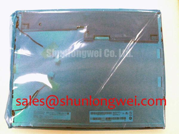
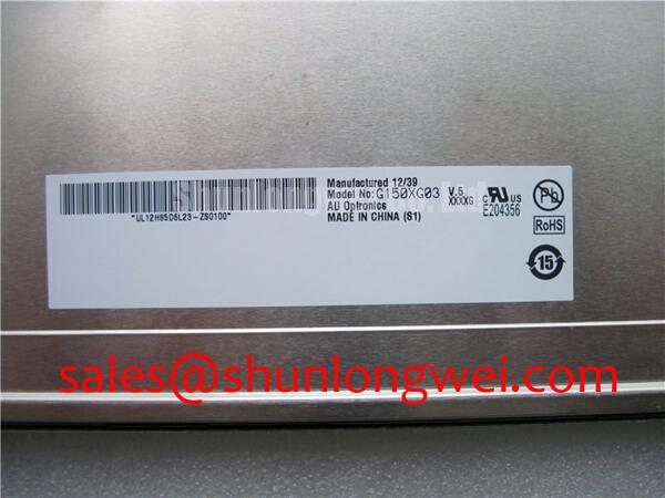
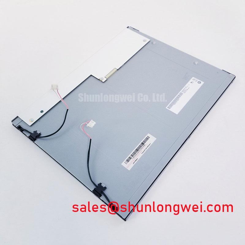
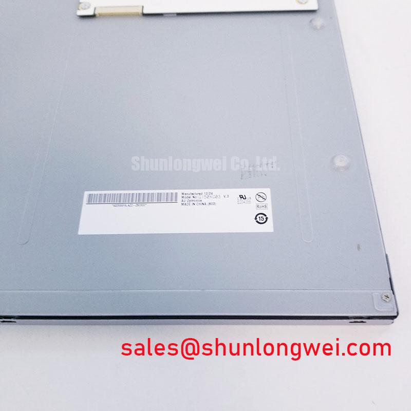
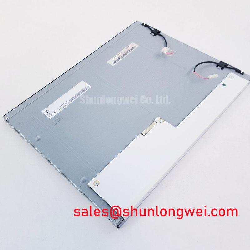
The G150XG03 V4 is an AUO TFT LCD Active Matrix Color Display Module identified here as an Industrial Grade LCD/HMI Panel. For repair work involving a substation protection terminal or SCADA dispatch console, a full screen test pattern is more informative than a boot logo because it exposes nonuniform regions that may remain hidden behind normal application graphics.
Use separate solid black, white, red, green, blue, and mid grey images. A black field helps reveal unwanted light leakage or areas of irregular illumination. White and grey fields expose luminance nonuniformity, while primary colour fields can reveal a signal path issue that affects one data component more noticeably than others. Record the observation with the panel in its intended bezel orientation, because pressure from the host enclosure can alter the visible result after installation.
Constant brightness depends on the complete display system rather than the panel alone. The system integrator should verify the original backlight driver, its enable control, dimming method, supply stability, and cable condition from the original equipment documentation. A drifting brightness level can be associated with the driver, its control signal, an interconnect, heat accumulation within the equipment enclosure, or the optical assembly. Comparing the unit against a known good display under the same source and driver conditions is more reliable than assigning a single cause from one symptom.
Heat near narrow panel edges deserves particular attention when the display sits behind a tightly fitted metal bezel. Design Consideration: provide a chassis thermal path that avoids concentrating heat alongside one edge of the display, because uneven enclosure temperatures can become visible as brightness variation across a large bright image. The effectiveness of any heat spreader, interface material, or mounting rail must be validated in the finished equipment with its actual driver loading, ambient conditions, bezel structure, and ventilation arrangement.
Backlight lifetime figures, L70 values, B50 values, and MTBF curves are not stated in the verified factory information provided for this product. Do not use a generic LED endurance figure as the service life of the G150XG03 V4. For a maintained console, practical reliability verification focuses on repeatable measurements: compare white field brightness at the same driver setting, check for progressive colour imbalance, observe the display after thermal soak, and retain baseline photographs for later service comparison.
💡 Bench Tip: Disconnect system power and use ESD controls before handling the panel cable, then seat the flat cable squarely and lock the connector without twisting the cable tail.
Where a console includes a front window or added optical bonding layer, inspect the stack as a system. Condensation marks, contamination at the visible edge, or a locally stressed cover lens can resemble an internal display defect. Optical bonding, gasket design, and enclosure sealing are system-level choices, so their material construction and environmental capability require verification against the equipment drawing and the selected bonding process rather than being attributed to this AUO module.
Chassis M3 Fastener Torque and Optical Mura Defects
Loosen and retighten the host bezel in a controlled cross pattern while a uniform grey image is displayed, watching for areas that brighten, darken, or change appearance as clamping force changes. This immediately distinguishes a pressure-sensitive visual effect from image data corruption, backlight instability, or a damaged signal cable.
A local dark or bright region is often described as mura, but the observation alone does not establish its origin. Mechanical preload, bezel geometry, mounting surface flatness, support points behind the panel, and the location of neighbouring hardware all deserve inspection. Any panel replacement should preserve the original mechanical stack order, including spacers, brackets, insulating films, and cable guides.
The 0.35–0.45 N·m range sometimes used for M3 display-related hardware is a Design Consideration, not an AUO factory torque specification for the G150XG03 V4. The final torque depends on the screw grade, thread engagement, bracket material, washer arrangement, bezel stiffness, and original equipment requirements. Use a calibrated torque tool only after confirming the fastener specification on the host chassis documentation.
Cross-pattern tightening helps distribute load progressively around the display perimeter. Avoid forcing one corner fully down while the other fastening points remain loose. If a uniform-field image changes as screws are tightened, stop and inspect for an incorrect spacer height, warped bezel, trapped cable, displaced gasket, or mounting rail interference. Continuing to increase torque can conceal the installation error while making the visual result worse.
Cold environmental behaviour also requires system-level evaluation. Liquid crystal response can appear slower at low ambient temperature, and the visible effect can include delayed transitions or trailing around moving graphics. That behaviour should be evaluated with the original controller timing, panel supply sequence, enclosure temperature, and any installed heater control. Do not infer a supported low-temperature operating range or heater requirement for the G150XG03 V4 from a generic industrial display practice.
For high-voltage substation protection and dispatch interfaces, the display is often housed in a front assembly that also carries keys, indicators, communication ports, and shielding features. These parts can transfer mechanical stress into the bezel if their alignment is poor. Inspect the chassis opening with the display removed, verify that mounting points sit on a common plane, and ensure cable routing does not pull sideways on the connector after the enclosure is closed.
A repair bench should also separate image persistence concerns from physical optical effects. A faint retained image after a power event may relate to the host power-down sequence, a controller state, or the characteristics of the displayed content. A pressure-related mura pattern typically changes when the panel is reseated or when mounting load changes. Treat both observations as evidence to be tested rather than as a final diagnosis.
VESA and JEIDA Data Mapping Alignment and Even Odd Channel Signal Integrity
Capture the panel supply ramp, panel enable control, and display clock at the original connector while reproducing the white screen, split screen, colour inversion, or unstable image symptom. These observations reveal whether the fault follows power sequencing, source timing, cable integrity, or data mapping instead of assuming that the LCD module is responsible.
The available product information identifies the G150XG03 V4 as a TFT LCD active matrix colour display module, but it does not provide a verified logic supply voltage, interface type, pin assignment, data mapping option, timing table, or connector part number. The system integrator should verify the required supply voltage, interface standard, pinout, mapping format, and power sequence from the original panel documentation and the host equipment schematic.
VESA and JEIDA mapping are not interchangeable labels. A mismatch can produce incorrect shades, swapped colour information, unusual greys, or image segmentation even when the display appears to receive a valid clock and active data stream. Verify the transmitter configuration against the original panel requirement, then compare a known good image source using controlled red, green, blue, grey, and checkerboard test patterns. Photographing those patterns makes colour-related differences easier to review across multiple repairs.
Signal integrity must be checked as a complete channel. Inspect connector latch engagement, cable fold radius, grounding continuity, nearby switching conductors, and any intermediate board-to-board connection. An intermittent horizontal line, pixel sparkle, unstable colour region, or split image may indicate a poor contact, damaged cable conductor, mapping mismatch, timing issue, or interference path. Oscilloscope comparison against a known good signal path provides more dependable evidence than a visual guess.
Engineering Recommendation: route high-speed differential display conductors as controlled pairs and preserve their intended pair relationship through connectors, adapters, and cable assemblies. The appropriate impedance target, routing geometry, length matching, clock margin, and hold-time margin are determined by the verified panel interface specification and the host transmitter design. Validate the completed assembly under actual equipment conditions, especially when the cable has been replaced or rerouted.
Power sequencing should receive the same attention as data routing. A white screen, unstable start-up image, or residual image during shutdown can arise when panel logic, source data, backlight control, and enable signals do not transition in the expected relationship. Measure each relevant rail and control line with the original harness installed. Then compare the sequence with the original equipment documentation and correct the host-side condition rather than applying an assumed timing value to the panel.
Wide-angle viewing performance, colour appearance, and contrast behaviour are visible system results that depend on panel technology and the surrounding optical stack. The available product information does not specify IPS, MVA, viewing angle, contrast ratio, colour gamut, or response-time characteristics for this exact model. A service inspection should therefore use the installed viewing geometry and the intended screen content, particularly where operators read alarms, protection status, or SCADA values from more than one position.
Shielded Flat Cable Grounding Across Connector Shells
Move the display cable gently while a fine checkerboard or grey raster pattern is active, then observe whether noise bands, pixel flicker, or image movement changes with cable position, connector pressure, or proximity to nearby power wiring. This test quickly identifies whether the disturbance deserves cable and grounding investigation before the display module is removed.
High-voltage substation protection and SCADA dispatch equipment can contain power conversion, communication, relay, control, and monitoring circuits in close proximity. The display cable path should be examined for coupling routes from switching conductors, power harnesses, chassis seams, or improperly terminated shields. A visible horizontal noise band can be related to common-mode interference, a loose shell connection, a cable fault, an unstable signal reference, or host-side video timing. Each possibility requires measurement and isolation.
Design Consideration: where the original cable assembly uses shielding, maintain a low-impedance chassis bonding path through the intended connector shell and cable termination arrangement. A shield that is interrupted by an unsuitable adapter, painted mounting surface, loose bracket, or incomplete connector engagement can reduce the effectiveness of the original system design. The equipment designer should validate grounding continuity and noise performance in the final enclosure.
Ferrite components can be useful in certain system layouts, but they are not a universal repair action. Their material selection, placement, and effect depend on the noise spectrum, cable current balance, chassis grounding scheme, and enclosure construction. Additions should be verified with actual display behaviour and measured interference response, ensuring that they do not impose cable stress or interfere with connector seating.
Inspect the cable route for sharp bends, compression by covers, abrasion against chassis edges, and unsupported movement. A cable that appears intact can still have a compromised contact or shield termination. Substitution with a known good compatible cable assembly, followed by the same image-pattern test, is a practical way to separate a cable-path issue from a panel-side concern.
Connector shell bonding is only one part of a stable visual system. The source board ground reference, power return path, front bezel contact, cable clamp arrangement, and enclosure seams can all influence susceptibility to noise. For a broader framework on display installation, fault isolation, interface checks, and environmental integration, see Industrial Display & HMI Solutions.
After reseating the G150XG03 V4, repeat the solid-colour, grey-field, and motion tests with the cabinet fully assembled. A result that is stable on the open bench but changes after closing the door points toward installation pressure, cable routing, shielding contact, or enclosure grounding. This evidence-based sequence supports repair decisions without assigning unsupported electrical, optical, lifetime, or environmental specifications to the AUO display module.