




Content last revised on September 30, 2026
Flashlight Dark Shadow Optical Diagnostic to Isolate Logic and Backlight Failure Modes
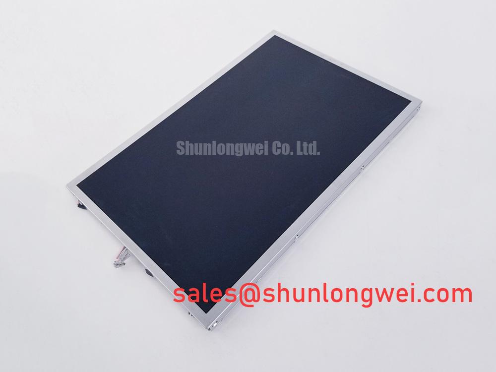
Switch on the display and place a flashlight at an oblique angle against the viewing surface while the host system sends a known image; a visible dark shadow with faint image detail can separate a non-illuminated screen from a signal-path or panel-drive problem without immediately removing the module.
Use a controlled three-stage bench check. First, confirm whether the host produces a stable test pattern and whether the display changes when the source image changes. A completely uniform dark field requires a different inspection path from a panel that shows partial characters, a frozen image, or uneven content. Second, repeat the test with the flashlight moved across the active area. Image detail visible beneath the dark surface suggests that the image data path may still be active while the illumination path requires investigation. Third, compare the same signal path with a known-good display or an approved test interface, keeping the cable routing and host configuration unchanged.
This optical check cannot by itself identify a specific failed component. A dark region may also result from a connector contact problem, an incorrect power sequence, a disabled backlight control signal, or damage near the panel driver area. Inspect the mating connector for contamination, incomplete insertion, bent contacts, and mechanical strain. Confirm that the host is using the interface format required by the original equipment documentation rather than assuming that a physically similar connector has the same electrical assignment.
For high-interference equipment, treat the display cable as a transmission path rather than a simple wire bundle. LVDS pairs should be routed as controlled differential structures with a continuous reference plane, consistent pair geometry, and minimal branch length. A 100 Ω ± 10% differential impedance and skew of no more than 50 ps may be used as a Design Consideration during a system-level signal-integrity review; these values are not stated factory specifications for G154I1-LE1. The final design team should verify eye opening, common-mode behavior, and clock stability at the actual cable length and connector arrangement.
JEIDA and VESA data ordering must be checked against the original controller configuration. A display can remain apparently functional while showing incorrect colors, shifted grayscale, or unstable image content when the bit mapping or pixel-clock polarity is wrong. Compare the red, green, and blue primary patterns separately, then inspect white, black, and mid-gray patterns. A localized line defect that remains fixed while the source image changes can require microscope-level inspection of the panel edge and its bonded driver region, but the flashlight test should be treated only as an isolation method, not as proof of a particular internal failure.
AUO provides information about industrial display and embedded-system technologies through its industrial display and embedded systems resources. For system-level HMI troubleshooting, engineers can also consult Industrial Display and HMI Solutions when reviewing enclosure, cable, thermal, and environmental interfaces.
Wide Temperature Operational Margin and Sub Zero Liquid Crystal Response
Place the display under controlled thermal observation and record image recovery, gray transitions, startup behavior, and visible uniformity while the ambient condition changes; do not attribute a slow cold image response to the panel alone before checking the controller, supply sequencing, cable impedance, and enclosure heat path.
The supplied factory parameter set identifies G154I1-LE1 as an AUO TFT-LCD active matrix color display module, but it does not provide a verified operating temperature range, gray-to-gray response specification, heater requirement, epoxy seal qualification, or 50,000-hour MTBF value. Those figures must not be assigned to this model without the applicable manufacturer documentation. The often-used test envelope of −30°C to +85°C can be used only as a Design Consideration for system validation when the original equipment specification requires it; it is not an official rating established by the supplied data.
Liquid-crystal viscosity normally increases as temperature falls, which can lengthen visible gray transitions and cause motion smearing during cold startup. A service engineer can distinguish this behavior from a data fault by displaying a sequence of static gray fields and moving contrast patterns while monitoring whether the image gradually improves as the assembly reaches thermal equilibrium. A stable image with slower transitions points toward a thermal response characteristic, while intermittent rows, random color changes, or loss of synchronization require inspection of the signal and power paths as well.
Cold-start evaluation should include the complete display assembly, not just the panel. Record the controller startup order, backlight enable behavior, supply rise time, cable flexibility, and enclosure temperature near the panel perimeter. If the equipment uses a heater strip, its control loop must be evaluated for local hot spots, condensation risk, and mechanical stress. The heater design is system-dependent, and no heater power, control temperature, or warm-up period is specified for G154I1-LE1 in the supplied factory data.
Thermal cycling can also expose mechanical problems that are invisible at room temperature. Differences in expansion between the bezel, mounting frame, cable support, and display assembly may create localized pressure or change connector contact force. Inspect the image at the center and perimeter after each thermal transition. Mura, corner shading, or a changing dark-field pattern should be compared with the panel in a relaxed fixture before a replacement decision is made.
For a surgical navigation display or ultrasound diagnostic console, the system integrator should verify the required luminance, contrast, response time, temperature range, cleaning-fluid compatibility, and regulatory system qualification from the original equipment documentation. The LCD module itself should not be represented as independently certified for the complete medical device. Its suitability depends on the controller, optical stack, enclosure, software, power supply, and final system validation.
Surface Anti Glare and Anti Reflective Readability in High Ambient Light
Display a black field, white field, and mid-gray field under the intended room lighting, then vary the viewing angle and remove external reflections to determine whether lost detail comes from surface glare, grayscale behavior, backlight nonuniformity, or a signal-level problem.
The supplied specification identifies the construction as a TFT-LCD active matrix color display module but does not confirm an anti-glare treatment, anti-reflective coating, luminance value, viewing-angle specification, TN, IPS, or MVA optical mode. Do not assign a symmetric 85°/85°/85°/85° viewing cone to G154I1-LE1 without an applicable AUO datasheet. Optical behavior should be verified on the actual unit or against the original panel documentation.
High ambient illumination can reduce perceived contrast even when the electronic image signal is correct. Use the same text, grayscale, and diagnostic images viewed through the installed cover glass or bezel aperture. Reflections from protective windows, recessed bezels, indicator lamps, and nearby metal surfaces can produce apparent image washout. The enclosure design should control the light path without creating pressure on the display surface or restricting the panel’s thermal expansion.
TN grayscale inversion, if present in a particular panel design, should be assessed by viewing neutral gray patches from above, below, and both sides. A change in apparent gray level with viewing direction is an optical characteristic to document, not automatically a display fault. Engineers comparing a candidate replacement with the original should evaluate the same image at the same distance, ambient illumination, cover-glass condition, and backlight setting. A similar diagonal size or connector position does not prove equivalent optical performance.
Backlight control also requires measurement at the host interface. If the equipment uses PWM dimming, a 200 Hz to 1 kHz range may serve as a Design Consideration during system-level flicker and acoustic-noise evaluation, not as a confirmed G154I1-LE1 specification. The controller should be checked for duty-cycle linearity, enable polarity, startup timing, and its response to an open or short backlight condition. The LCD module’s supplied data does not confirm a particular LED current, LED forward voltage, dimming frequency, or protection threshold.
💡 Pro Tip: Keep differential display pairs closely matched in length and routing environment, then verify the pixel clock and data eye at the panel connector rather than relying only on a clean waveform at the controller.
Backlight fault diagnosis should include the driver output, enable command, current regulation behavior, and fault-reporting path where the equipment provides one. An open LED string, a shorted string, an overtemperature event, or a disabled controller can produce similar dark-screen symptoms. Capture the fault state and compare it with the service documentation before replacing the LCD module. The available factory information does not provide a guaranteed backlight lifetime, failure rate, or MTBF figure for this model.
Industrial Bezel Mechanical Envelope and Mounting Screw Torque Review
Remove external loading from the bezel and inspect the display while gently changing the fixture condition; a dark corner, bright pressure mark, or changing mura pattern should be compared with the module resting without frame distortion before tightening any replacement assembly.
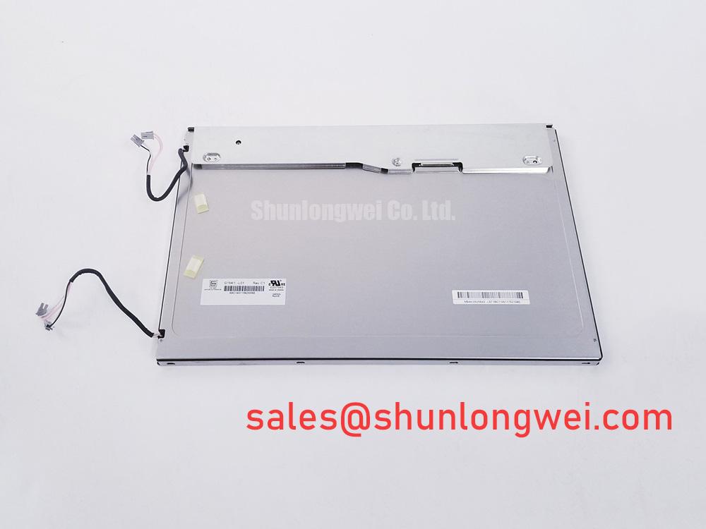
The supplied factory information confirms the package as a TFT-LCD active matrix color display module, but it does not include verified outer dimensions, active-area dimensions, mounting-hole coordinates, bezel envelope, panel thickness, connector location, or fastener specification. These physical values must be taken from the original equipment drawing or the applicable AUO mechanical drawing. A replacement should not be selected by diagonal size alone.
Measure the chassis opening in multiple locations and compare it with the original panel, including corner radii, cable exit clearance, front-surface position, and the depth available for the controller and backlight connection. The bezel should support the intended non-display frame area without pressing the active area. Foam, gasket, and clamp placement should distribute load evenly and should not force the panel against a rigid cover window.
A cross-pattern tightening sequence can help reduce uneven frame loading. The requested 0.35 to 0.45 N·m range for M3 fasteners may be used only as a General Industry Design Consideration when the chassis, screw material, insert type, washer arrangement, and original drawing support it; it is not an official mounting limit for G154I1-LE1. The system engineer should validate the actual torque with the complete fixture and inspect the display for pressure-induced optical change after assembly.
Vibration and shock evaluation should focus on cable retention, connector support, fastener loosening, bezel contact, and changes in image uniformity. The display module should not be treated as qualified for a particular medical, industrial, or transportation vibration profile unless the complete assembly has been tested to the relevant equipment requirement. Mechanical isolation, strain relief, and enclosure stiffness are system design matters rather than intrinsic factory claims for this model.
When integrating G154I1-LE1 into a high-precision surgical navigation or ultrasound diagnostic display, verify the original panel’s electrical interface, optical behavior, mechanical envelope, backlight driver requirements, and software timing before authorizing the substitution. For a neutral comparison point during sourcing, engineers may review HLM8620-6, while treating all interface, optical, and mechanical data as part-specific requirements that must be matched rather than assumed equivalent.