Content last revised on September 10, 2026
Grayscale Inversion Mitigation & Optimal Viewing Direction Alignment
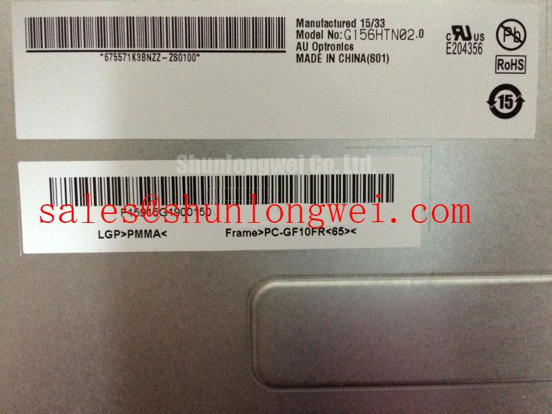
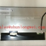
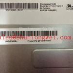
The supplied factory identification confirms the G156HTN02.0 as an AUO industrial TFT LCD module, but it does not establish panel-mode details, viewing-angle limits, interface timing, supply rails, or luminance values in the available structured factory information. A technician should therefore verify the original panel documentation and host-controller signal requirements before assuming Normally White TN behavior, an IPS or MVA viewing cone, or a particular LVDS or TTL timing arrangement.
When a replacement display produces acceptable graphics from one physical position but shows shifted grayscale, reduced contrast, or tonal inversion from another, first compare the panel orientation with the removed unit and the intended operator sightline. This is a Design Consideration: display mode, polarizer orientation, cabinet angle, cover lens reflections, and source-image gamma can all influence perceived image quality. A screen that appears washed out at an oblique angle does not by itself prove a panel fault.
Anti-glare surface treatment should also be evaluated in the assembled equipment rather than judged only on a powered bench. Strong overhead lighting can reveal reflections, haze, and contrast loss that are not obvious in a dim workshop. For equipment such as railway passenger information terminals or cab signalling displays, engineers often assess readable viewing direction, enclosure glass condition, and ambient-light exposure as a complete optical path, subject to the requirements of the original system.
Interface verification should begin at the host side. Check that the display cable is fully seated, that its latch or retention method is intact, and that the original controller is supplying the expected signal format. Clock instability, inadequate data hold timing, cable damage, connector contamination, or ground-reference disturbance may create intermittent pixels, image shimmer, color errors, or an unstable picture. The system integrator should verify transmitter timing margins across the actual operating-temperature range using the original panel documentation and measurements from a known-good signal path.
⚠️ Field Alert: Disconnect system power and allow stored energy to discharge before inserting or removing the display cable to avoid signal-pin stress during service.
Chassis M3 Fastener Torque Considerations (0.35–0.45 N·m) for Optical Mura Defects
Before tightening the display into its chassis, place the module on a clean, flat work surface and confirm that the surrounding metalwork does not preload the bezel, pinch the cable, or push against the active viewing area. Local pressure can appear as uneven brightness, dark shading, color variation, or pressure marks after installation. These observations require mechanical inspection; they should not be assigned to a single internal cause without comparison against the removed panel and the equipment enclosure.
A cross-pattern fastening sequence is a Design Consideration for panels held by M3 hardware. The 0.35–0.45 N·m range is a general industry starting reference for controlled M3 fastening, not an AUO factory torque rating for this model. Final torque, washer selection, standoff height, bracket flatness, thread engagement, and tightening sequence must be determined from the host equipment design and verified against the original panel documentation.
Do not use mounting screws to pull a distorted chassis into alignment. Instead, loosen the assembly, inspect standoffs and retention brackets, correct the mechanical interference, then refit the module evenly. This approach helps distinguish a panel-related optical issue from stress imposed by the machine cabinet. A powered inspection using uniform gray, white, and black images is useful after each mechanical change because subtle pressure artifacts can be easier to see on a uniform field than on normal application graphics.
Where the host controller offers PWM backlight control, its frequency and duty-cycle behavior remain system-level characteristics rather than confirmed specifications of the G156HTN02.0. As a Design Consideration, engineers should evaluate brightness transitions, visible flicker, and any audible behavior from associated electronics within the original controller and power architecture. A nominal PWM range of 200 Hz to 1 kHz is commonly evaluated in industrial display systems, but the required setting is determined by the display assembly, backlight driver, controller firmware, and validation results.
Constant Luminance Output Control & Backlight Lifetime Verification
Brightness drift should be investigated through measured behavior rather than assumed life predictions. The available factory information identifies this product as a TFT LCD display module but does not provide a confirmed backlight technology, luminance rating, LED lifetime, L70 value, B50 value, thermal limit, or heat-spreader requirement. Those values must be obtained from the applicable original AUO documentation for the exact panel revision before they are used in maintenance planning.
When a display powers on with a dim image, intermittent illumination, or brightness variation, inspect the external factors first: panel cable seating, controller power rails, backlight-enable behavior, brightness-control signal, connector condition, and the equipment’s thermal path. A dim panel can be associated with more than one condition. Comparison with a known-good panel and controlled measurement at the original display connector provide a more reliable service direction than visual judgment alone.
Heat management is a Design Consideration at the equipment level. If the host enclosure uses edge rails, brackets, or conductive chassis surfaces near the panel, engineers should assess whether those parts create localized thermal loading or mechanical stress during continuous operation. The objective is to maintain stable operating conditions without imposing distortion on the display module. The final arrangement depends on enclosure geometry, airflow, nearby power devices, duty cycle, and the temperature limits documented for the original panel.
For environmental assessment methods that extend beyond a single replacement panel, the practical reference is the wider equipment context. The Industrial Display & HMI Solutions resource can support evaluation of enclosure conditions, system maintenance access, and display integration variables. It should not be treated as a substitute for the model-specific factory documentation required to establish electrical, optical, or lifetime limits.
Incoming Benchtop Inspection: Panel Bonding and Interface Integrity
At incoming inspection, begin with the panel disconnected and inspect the front surface, bezel, mounting areas, rear housing, and accessible cable interface for handling damage or mechanical strain. The available official structured information does not confirm a COG, TAB, or ACF construction for the G156HTN02.0. Do not infer an internal bonding method from a visible display symptom. Internal construction and repairability should be verified only through applicable manufacturer documentation.
A useful bench sequence is to power the panel only through the correct original system interface after the required electrical compatibility has been confirmed. Display full red, green, and blue image fields, followed by white, medium gray, and black fields. Observe whether lines, missing subpixels, unstable regions, tint changes, or brightness nonuniformity remain fixed in position across the test patterns. A fixed defect pattern can help isolate the affected image area, while behavior that changes with cable movement may warrant closer inspection of the connector, cable, and host-side signal path.
Use a flashlight at an oblique angle with the panel powered and then with the panel unpowered to distinguish surface reflections, cover-lens marks, and backlight-related dark regions from active-image anomalies. This is a diagnostic aid, not a definitive failure classification. If the screen shows a faint image only under external light, verify the backlight-control path and panel power conditions. If the screen is illuminated but has corrupted content, compare the source timing and data path against a known-good controller output.
Claims relating to direct-sunlight contrast, including a contrast ratio above 500:1 at 50,000 lux, cannot be assigned to this model from the supplied factory data. The anti-glare performance, optical contrast, and outdoor readability of the assembled terminal should be verified under the relevant installation lighting conditions. For railway passenger information systems and cab signalling displays, such assessment remains a compatibility evaluation, subject to the original equipment’s safety, enclosure, and approval requirements.