
Content last revised on October 27, 2026
Benchtop Waveform Tuning: Optocoupler vs Digital Coreless Transformer Isolation on GD400HFT120C2SN
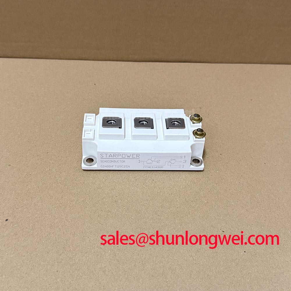
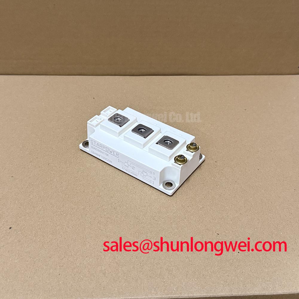
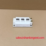
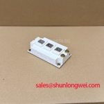
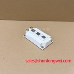
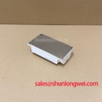
Manufacturer: StarPower | Model: GD400HFT120C2SN | Official Specification: 1200 V, 400 A | Package: Power Module | Category: IGBT Module
I check the isolated driver supply and gate-to-emitter waveform before reconnecting the power stage, looking for unintended pulses while the switching command remains inactive. For the GD400HFT120C2SN, this separates a driver-side disturbance from a suspected module fault without immediately exposing the assembly to full bus energy. Use appropriately rated differential measurement equipment and keep the probe connection compact enough to avoid mistaking pickup for a real gate excursion.
Design Consideration: Compare optocoupler and digital coreless-transformer drivers by their documented common-mode transient immunity, propagation behavior, isolation classification, and output response during supply disturbances. Neither isolation technology alone establishes suitability. Reinforced insulation requirements belong to the complete insulation coordination assessment; the module’s 1200 V rating does not establish a driver barrier test voltage or CMTI requirement.
Inspect the isolation boundary for contamination, misplaced conductors, and copper features that compromise the intended creepage or clearance. Correlate unwanted gate activity with switch-node transitions and isolated-supply movement before changing gate damping. When reviewing adjacent power-conversion stages, the FZ2400R12HE4_B9 comparison provides separate device context, not a shared driver prescription or proof of interchangeability.
Benchtop Waveform Tuning: Static and Dynamic Current Distribution on GD400HFT120C2SN
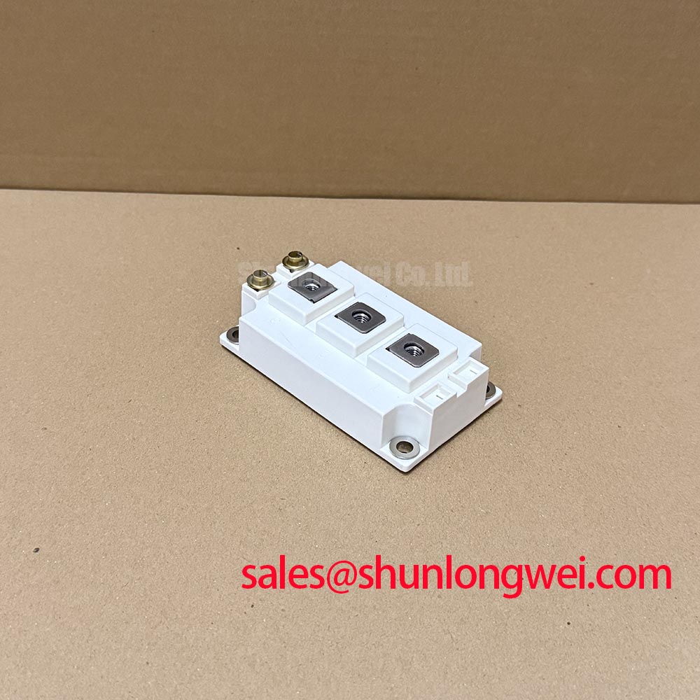
Map the main terminals and gate connections against the module connection drawing before comparing current paths. A matching current rating does not establish matching topology, terminal positions, mounting geometry, or driver compatibility. A cross-model review involving CM900DUC-24S should therefore remain a compatibility assessment rather than a replacement recommendation.
Design Consideration: A positive temperature coefficient of on-state voltage can assist steady-state current sharing where the device characteristic exhibits that behavior. It should not be assumed across every operating point or treated as an independently verified characteristic of this module. For parallel assemblies, compare device characteristics at relevant temperatures, equalize thermal interfaces, and examine branch currents under the actual load profile.
Dynamic sharing depends on gate-loop symmetry, driver timing, and power-path inductance. Compare switching transitions with equivalent probe arrangements; unequal measurement loops can obscure the imbalance being investigated. Check busbar seating, cable strain, terminal spacing, and fastening against the assembly instructions. Field Alert: Do not pull a misaligned busbar into position by tightening the module terminals.
In a utility-scale 1500 V central solar inverter assessment, this 1200 V module requires a topology that keeps individual device stress within its limits; direct blocking of the full bus is not acceptable.
Field Diagnostics and Commissioning: Assessing Suspected Substrate Damage Around GD400HFT120C2SN
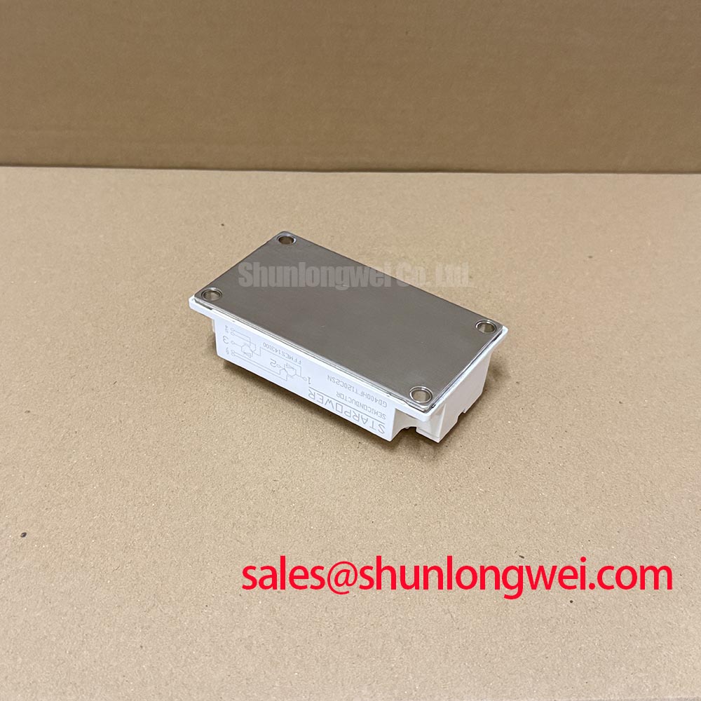
Isolate the module from connected driver electronics before evaluating terminal-to-baseplate insulation under an approved service procedure. Inspect accessible surfaces for conductive dust, moisture tracks, damaged terminal insulation, and mounting distortion. These observations help distinguish external leakage paths from faults requiring specialist examination, but they cannot establish the condition of an inaccessible ceramic substrate.
Design Consideration: An insulation-resistance reading does not prove the absence of internal microcracks. Apply only the manufacturer-authorized test connections, voltage, duration, and acceptance criteria; an improvised high-voltage test can stress connected circuitry or exceed the intended maintenance procedure. Record environmental conditions and instrument configuration so subsequent measurements remain comparable.
Material references explain packaging principles without identifying this module’s construction. Background on silicon nitride ceramic substrates and thermal packaging and polyphenylene sulfide engineering plastic must not be read as confirmation that either material is present in the GD400HFT120C2SN.
After cleaning or mechanical correction, reassess accessible insulation paths and thermal contact using the equipment service procedure. Persistent leakage or mechanically sensitive behavior warrants further examination rather than an automatic diagnosis of ceramic cracking.
GD400HFT120C2SN Operational Boundaries: Evaluating Desaturation Detection Limits
Capture the interval from abnormal collector-emitter voltage to gate shutdown when evaluating desaturation protection. Separate turn-on into an existing short circuit from a fault developing during conduction: blanking, sensing behavior, and current rise differ between these conditions. Use a controlled qualification setup rather than deliberately shorting an installed converter.
Design Consideration: Set the complete protection response against documented device short-circuit capability at the relevant operating conditions. A generic detection-time target is not a verified survival limit. Evaluate sensing delay, filtering, driver response, and turn-off together. Where the driver supports staged soft shutdown, assess the trade-off between limiting inductive overshoot and extending fault-current duration.
Inspect the commutation path before changing protection thresholds. The discussion in Mastering Power System Dynamics supports analysis of stray inductance and snubber behavior; component choices remain dependent on measured switching stress.
For braking-chopper assessments, evaluate resistor energy absorption and repetitive semiconductor heating separately. Do not substitute a diode surge-current rating, ITSM, for IGBT short-circuit capability. Permit restart only under the equipment’s validated fault-reset and thermal-recovery procedure.