
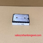
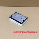

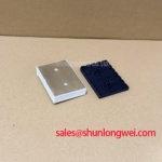
Content last revised on October 27, 2026
Field Diagnostics & Commissioning: Suppressing Cres-Induced Gate-Voltage Spikes in K429B7002 Topologies
I check the equipment schematic and identify the control terminals before placing a probe on the K429B7002 installation. The supplied voltage and current descriptions, “Standard Industrial Rating” and “Standard Operating Current,” are qualitative placeholders, not numerical electrical limits. The K429B7002 product reference should therefore be matched to the original equipment documentation before a replacement decision. The following gate-drive discussion is a Design Consideration for a documented insulated-gate switching topology, not confirmation of this module’s internal circuit.
In that topology, unwanted gate movement during opposite-switch transitions deserves direct measurement. Probe gate voltage relative to its designated driver return, using a measurement arrangement suitable for the common-mode voltage and switching environment. Compare the disturbance with the switching-node transition and driver output. A narrow pulse alone does not establish cross-conduction; correlated current measurements and measurement-loop checks help distinguish actual switching from probe pickup.
A dedicated active Miller clamp can provide a low-impedance discharge path during the off state, but its effectiveness depends on clamp timing, connection inductance, and driver compatibility. Negative gate bias is another system-level option only where the device and driver permit it. Neither a bias voltage nor a clamp threshold can be assigned from the model designation. Keep the discharge loop compact and validate the resulting gate excursions against documented limits under representative operating conditions.
Driver supply behavior also belongs in this investigation. For an equipment circuit using a bootstrap supply, inspect charging opportunities, capacitor condition, supply droop, and diode recovery during the actual operating sequence. Check optocoupler or digital-isolator common-mode transient immunity against measured switching conditions. A disturbed driver supply or isolation signal can resemble a module fault, so changing gate resistance alone may leave the initiating problem untouched.
Benchtop Waveform Tuning and Insulation Screening: Investigating Possible Ceramic DBC Substrate Micro-Cracks on K429B7002
Disconnect external electronics and establish the permitted insulation-test connections before applying an insulation tester to the assembly. Design Consideration: terminal-to-baseplate testing requires the manufacturer’s test voltage, terminal grouping, duration, and acceptance criteria. An arbitrary high-voltage test is not a substitute for that procedure. This heading identifies an inspection topic; it does not establish that K429B7002 contains a ceramic DBC substrate, and an insulation-resistance reading cannot independently confirm or exclude internal microcracking.
Inspect accessible insulation surfaces for conductive dust, moisture tracks, damaged barriers, and displaced insulating hardware. Record environmental conditions alongside measurements because surface contamination can affect leakage without proving an internal defect. Creepage and clearance checks should follow the equipment’s insulation design and applicable requirements, rather than an improvised spacing rule. After a cold assembly enters a warmer, humid workspace, allow condensation to clear before electrical evaluation.
Packaging information needs the same separation between general mechanisms and product identity. The reference on flip-chip packaging and copper-pillar interconnect concepts provides background on interconnection approaches; it is not evidence that this module uses them. For maintenance decisions, accessible mounting surfaces, insulation barriers, and the prescribed assembly process provide more actionable checks than assumptions about hidden construction.
Waveform tuning should follow the actual power circuit. If the equipment schematic uses phase-angle control, compare firing commands with conduction intervals and load-current behavior. If a DC link is present, assess ripple and capacitor condition at the relevant operating points. An RC snubber should be evaluated against measured ringing, repetitive energy, and component heating, with its values determined by the system designer. These circuit checks address electrical stress; they do not constitute a substrate-health test.
Maintenance Note: Trend terminal and heatsink temperatures under comparable load conditions, and check airflow before attributing a temperature increase to the module. Schedule cleaning and thermal-interface inspection around contamination, operating duty, and equipment instructions rather than an invented service interval. During an authorized teardown, inspect interface coverage and mounting condition, then reassemble using the documented material and tightening procedure.
K429B7002 Operational Boundaries: Evaluating PCB Symmetry Considerations for Dual IGBT Limits
Trace the driver return and main-current return separately on the equipment drawing before evaluating PCB symmetry. Design Consideration: the following return-path discussion applies where a dual-switch circuit and auxiliary emitter connection are explicitly documented; neither a dual IGBT arrangement nor a Kelvin emitter terminal is established by the supplied K429B7002 information.
Where an auxiliary return exists, keep the driver reference from sharing the main emitter-current path beyond the intended connection point. Shared inductance can shift the apparent gate voltage during current transitions. Compare corresponding switching channels for return routing, gate-loop area, connector contact condition, and damping-component placement. Visual symmetry alone is insufficient: two similar-looking paths can have different electrical behavior because their current loops and reference connections differ.
Preserve the equipment’s isolation barriers when repairing a driver board. A shorter wire is not automatically a better repair if it crosses a required separation or moves the gate loop closer to a noisy conductor. Evaluate ringing with consistent probe placement and check whether it follows switching edges, driver supply disturbances, or load changes. Any damping adjustment should be checked for switching loss and device stress, not judged solely by a smoother oscilloscope trace.
Protection coordination also remains a system task. The Mersen Protistor high-speed semiconductor protection fuse resources provide a starting point for reviewing fuse selection and manufacturer application guidance. Compare fuse clearing behavior, let-through energy, available fault current, and circuit voltage with documented equipment requirements. A semiconductor fuse does not, by itself, establish short-circuit survival or enclosure containment for this module.
For switching-test context, The 1200 V CoolSiC™ MOSFET Advantage in Three-Phase Power Conversion discusses a different device technology and voltage class; its ratings must not be transferred to K429B7002. During compatibility assessment for electric material-handling equipment or forklift low-voltage traction controllers, match the original circuit, mechanical interface, and protection scheme. Where long motor cables are present, evaluate reflected-wave stress at the motor and converter terminals before selecting any filtering measures.
Preventing Spurious Faults: Pre-Installation Junction Screening: Forward-Conduction Guidelines for K429B7002
With the assembly isolated and stored energy verified discharged, map the main terminals from the approved circuit drawing before using a multimeter’s diode-check function. Engineering Recommendation: record readings in both polarities and identify connected resistors, capacitors, or protection components that could influence them. Only interpret an antiparallel-diode path when that path is documented; an assumed terminal arrangement can make a sound assembly appear defective.
A repeatable reading is useful screening evidence, not proof of rated blocking capability or switching performance. Compare results with the prescribed service procedure or a documented reference assembly under equivalent conditions. Unexpected conduction, unstable readings, or substantial channel differences justify further isolation of the circuit. They do not identify a particular internal failure mechanism without additional evidence.
Gate-leakage assessment requires more care than a continuity check. Where gate terminals are documented, use the specified test method and a controlled instrument that respects their electrical limits. A handheld meter generally cannot certify leakage across the operating range. Likewise, treat “Fo” as a fault-output designation only if the connector documentation defines it; do not infer a fault pin or its logic behavior from the heading.
Before controlled energization, reconcile the terminal map, mounting arrangement, driver connections, and protection wiring with the equipment service record. Record cold-screening results and the instrument settings so later maintenance has a comparable baseline. If an unexplained fault remains, investigate the external supply, driver, and sensing paths before repeating power-up attempts.