




Content last revised on November 10, 2026
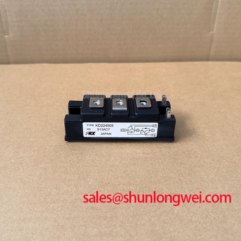
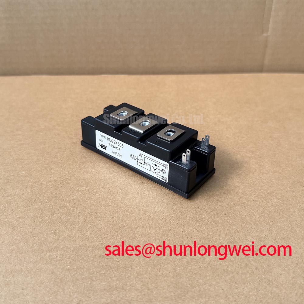
KD224505 Identification and Incoming Inspection
- Isolate the equipment, discharge stored energy, and match the KD224505 terminal markings to the equipment schematic before connecting test leads.
- Record cold diode-mode readings in both directions across each documented power path, with external parallel circuits disconnected.
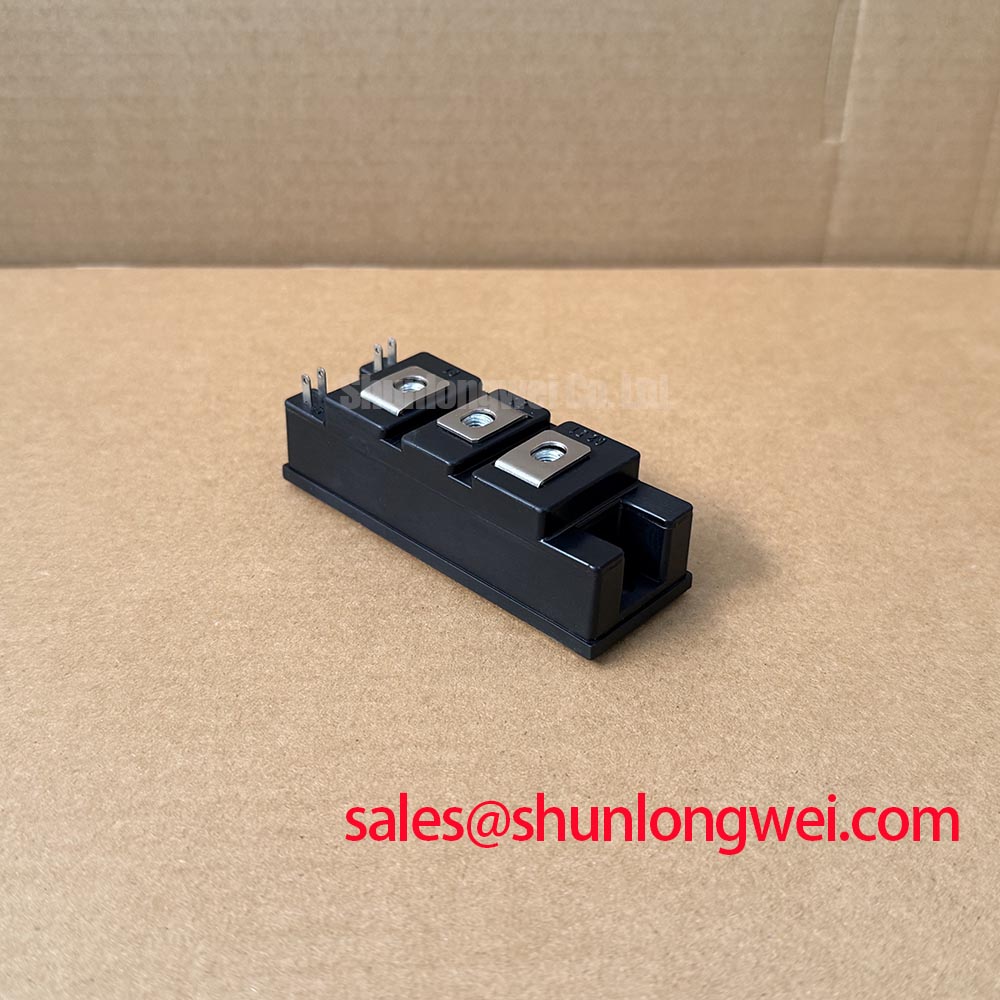
- Check the mounting surface, terminal condition, and cooling interface against the mechanical drawing.
- Identify any documented gate connections before testing; keep power-path measurements separate from gate-circuit checks.
The KD224505 is a SanRex (Sansha Electric) Thyristor / Diode Module. Incoming inspection should establish terminal identity and repeatable static measurements before powered evaluation. A handheld meter provides an initial comparison, not proof of reverse-blocking capability, surge withstand, or switching performance.
| Identification item | Product information |
|---|---|
| Manufacturer | SanRex (Sansha Electric) |
| Part Number | KD224505 |
| Package | SanRex Power Module |
| Configuration / Topology | Thyristor / Diode Module |
| Electrical and mechanical ratings | Consult Datasheet: numerical VRRM, IT(AV), ITSM, recovery characteristics, isolation test conditions, terminal arrangement, dimensions, and mounting torque. |
💡 Bench Tip: With the assembly isolated and discharged, use appropriate ESD handling and compare cold readings with a known-good unit at a similar temperature rather than applying a universal forward-voltage threshold.
KD224505 Operational Boundaries: Evaluating Reverse Recovery Charge Limits
Separate forward-conduction screening from reverse-recovery evaluation: the diode range on a multimeter cannot measure recovery charge or establish recovery softness. Design Consideration: a useful cold-test record identifies terminal pairs, probe polarity, instrument mode, and temperature conditions. Unexpected conduction should prompt isolation of connected snubbers, resistors, and other parallel paths before attributing the result to the module.
For powered commutation assessment, engineers should compare measured reverse-current peaks and recovery behavior with the applicable manufacturer test conditions. Reverse-recovery peak current, recovery time, and recovery charge describe different aspects of the waveform; recovery time alone does not establish soft recovery. Switching conditions, junction temperature, and measurement-loop effects influence the comparison.
Engineering Recommendation: capture current and terminal voltage together using suitable probes and a controlled test fixture. Examine ringing and voltage overshoot alongside the recovery current rather than treating an isolated current spike as a complete diagnosis. Commutation behavior can affect switching losses and conducted or radiated interference, but it does not establish equipment-level EMC compliance.
Use SanRex Sansha Electric Power Semiconductor Modules as the manufacturer reference point for device documentation. The Shindengen Power Semiconductor Modules & Diodes resource provides broader semiconductor context, not KD224505-specific ratings.
Assembly Integrity & Layout Architecture: Short-Circuit Protection Coordination for KD224505
Compare the protective fuse’s total clearing I²t with the semiconductor’s applicable withstand data under matching conditions. Design Consideration: pre-arcing I²t alone does not describe the complete let-through I²t during interruption. A coordination worksheet should include prospective fault current, circuit voltage, fuse clearing behavior, semiconductor initial temperature, and the specified surge waveform.
The non-repetitive surge-current rating, ITSM, is not a repetitive operating allowance. Following a surge, the permissible restart interval depends on the thermal state and subsequent loading. Where manufacturer transient thermal impedance data are applicable, the system engineer can assess pulse heating and junction-temperature recovery against the actual duty cycle. Fuse coordination cannot guarantee damage-free operation under every short-circuit condition.
Mechanical inspection belongs in the same assessment. Check baseplate contact, interface condition, terminal support, and fastener requirements before interpreting abnormal heating. Apply the documented tightening procedure rather than transferring torque values from a similar-looking housing. For general cooling-interface principles, the Mastering IGBT Thermal Management Technical Reference offers context; its IGBT discussion does not establish this module’s thermal ratings.
During replacement review, compare terminal mapping, circuit function, ratings, and mounting geometry explicitly. The GS-D200S is a separate catalog reference, not an established direct replacement for KD224505.
Preventing Spurious Faults: RC Snubber Network Optimization for KD224505
Evaluate the existing snubber against measured terminal-voltage transients before changing resistance or capacitance. Design Consideration: an RC network can moderate voltage rise and damp oscillation, but its discharge current, resistor pulse loading, and capacitor stress must remain compatible with the circuit. Component values belong to the system design, not to an assumed module-wide prescription.
Where a thyristor path is documented, distinguish gate-command behavior from voltage-induced triggering. Compare the gate signal with device voltage and current during the suspected event. Gate-path resistance measurements can reveal a discrepancy against a known-good assembly, but cannot establish trigger current, latching behavior, or turn-on current distribution. Any series reactor assessment should address current-rise control and its interaction with commutation and protection.
When evaluating compatibility with a high-voltage three-phase motor solid-state soft starter, designers should verify the required blocking arrangement, gate interface, insulation coordination, and protection sequence against the equipment schematic. A related catalog component such as PK130F-80 requires its own circuit-role and rating review; inclusion in the same power system does not imply interchangeability.
Before returning the assembly to service, compare controlled-test waveforms with the original circuit requirements and check snubber-component heating under representative operation. Retain the terminal map, cold-test record, fuse coordination worksheet, and waveform captures with the repair documentation.