IGBT Module Thermal Design: How Electric Vehicles Avoid Overheating and Power Derating
Every electric vehicle (EV) enthusiast knows the thrill of instant torque and silent, seamless acceleration. But some also know the frustration of “limp mode”—that sudden, unwelcome reduction in power during a spirited drive on a hot day, a strenuous uphill climb, or a fast-charging session. While the dashboard might display a simple warning, the root cause often lies deep within the power electronics: the traction inverter’s IGBT modules are overheating. This isn’t just a minor inconvenience; it’s a fundamental engineering challenge where performance, reliability, and cost converge. For design engineers and technical buyers, mastering IGBT thermal design is no longer optional—it’s the key to unlocking an EV’s full potential.
In this guide, we’ll move beyond surface-level explanations and dive into the core principles of IGBT thermal management in the demanding world of electric vehicles. We’ll explore why these components generate so much heat, how to analyze the thermal pathway, and what advanced strategies are being used to keep them cool under pressure, ensuring the driver has power on demand, every time.
The Root of the Problem: Why IGBTs Generate So Much Heat in EVs
An IGBT (Insulated Gate Bipolar Transistor) module is fundamentally a high-speed switch, the heart of the DC-to-AC inverter that drives the electric motor. Like any electronic component, it’s not 100% efficient. This inefficiency manifests as heat, and in an EV application handling hundreds of kilowatts, even a small percentage of inefficiency translates into a significant thermal load that must be managed.
Understanding Power Losses in IGBT Modules
The heat generated within an IGBT module primarily comes from two sources:
- Conduction Losses: When the IGBT is switched on, it’s conducting high currents from the battery to the motor windings. Although it behaves like a closed switch, it has a small internal voltage drop known as the collector-emitter saturation voltage, or VCE(sat). The power lost as heat during this phase is calculated as P_cond = VCE(sat) * I_c. In an EV, where motor currents can reach hundreds of amps, these losses are substantial.
- Switching Losses: An IGBT doesn’t turn on or off instantaneously. During these brief transition periods, both voltage across the device and current through it are high simultaneously, resulting in a momentary spike in power dissipation. These are the switching losses (Eon for turn-on, Eoff for turn-off). When multiplied by the switching frequency (often 10-20 kHz in EV inverters), these small spikes add up to a significant, continuous source of heat.
Additionally, the free-wheeling diode (FWD) packaged with the IGBT also contributes to losses, particularly during its reverse recovery phase. For a deeper dive into how IGBTs function, see our guide on deconstructing the IGBT’s hybrid structure.
The Vicious Cycle: Temperature’s Impact on IGBT Performance
Heat isn’t just a byproduct; it actively works against the IGBT’s performance. Most silicon-based IGBTs have a positive thermal coefficient for VCE(sat). This means as the chip’s junction temperature (Tj) rises, its on-state voltage drop increases. This, in turn, increases the conduction losses, which generates even more heat. If not controlled, this creates a dangerous thermal runaway cycle that can lead to component failure. To prevent this, the vehicle’s control unit will actively limit the current to the motor—the power derating or “limp mode” that drivers experience.
The Critical Metric: Understanding Thermal Resistance (Rth)
To solve the heat problem, we must first understand how heat travels. In power electronics, the key metric for this is Thermal Resistance (Rth), measured in Kelvin per Watt (K/W) or Celsius per Watt (°C/W). It quantifies how much the temperature of a component will rise for every watt of heat it generates. The lower the thermal resistance, the more effectively heat can be removed.
Breaking Down the Thermal Pathway: From Chip to Coolant
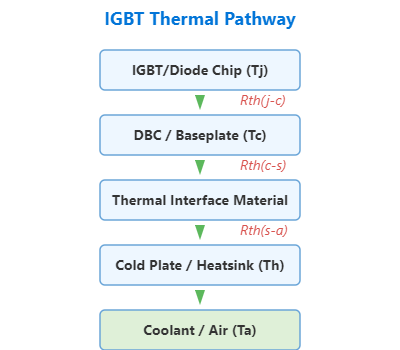
Heat generated at the microscopic IGBT chip junction must travel through several layers before it can be carried away by the vehicle’s cooling system. Each layer has its own thermal resistance, and they add up to create the total Rth.
The primary pathway includes:
- Rth(j-c) (Junction-to-Case): The resistance from the silicon chip itself to the module’s metal baseplate. This is determined by the module’s internal construction, including the die-attach material and ceramic substrate. This value is inherent to the IGBT module and is a critical figure of merit.
- Rth(c-s) (Case-to-Heatsink): The resistance across the Thermal Interface Material (TIM) that sits between the IGBT module’s baseplate and the system’s cold plate or heatsink. The choice and application of this material are crucial.
- Rth(s-a) (Heatsink-to-Ambient): The resistance from the heatsink/cold plate to the cooling medium (typically a water-glycol coolant in EVs). This is a function of the cooling system’s design (flow rate, cold plate structure, radiator size).
Understanding this chain is vital. As we explore in our article on why Rth matters for thermal performance, a bottleneck in any part of this chain will compromise the entire system.
How Rth Dictates Maximum Power Output
The relationship is governed by a simple but powerful formula: Tj = Ta + (P_loss * Rth_total), where Tj is the junction temperature, Ta is the ambient/coolant temperature, P_loss is the total power loss, and Rth_total is the sum of all thermal resistances. An IGBT module has a maximum allowable junction temperature (Tj_max), typically 150°C or 175°C for modern automotive-grade devices. The inverter’s control system constantly estimates Tj. If it approaches Tj_max, the controller reduces P_loss by limiting current, thus preventing catastrophic failure. This means that to maximize sustained power output, engineers must minimize the total Rth.
Advanced Thermal Management Strategies in Modern EV Inverters
The race for smaller, lighter, and more powerful EV inverters has driven incredible innovation in thermal management, both within the IGBT module and at the system level.
At the Module Level: Innovations in IGBT Packaging
IGBT manufacturers are fighting the thermal battle with sophisticated packaging technologies designed to lower Rth(j-c) and improve reliability.
| Innovation | Description & Advantage |
|---|---|
| Direct / Double-Sided Cooling | Instead of a traditional baseplate, these modules expose the top and/or bottom ceramic substrates directly to the coolant via a specialized cold plate. This eliminates the Rth of the baseplate and TIM, drastically improving heat transfer. Examples include Infineon’s HybridPACK™ DSC series. |
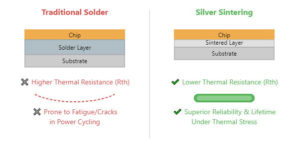
| Sintering Technology | Replaces traditional solder for attaching the silicon die to the substrate. Sintered silver has significantly lower thermal resistance and is far more resistant to the fatigue and cracking caused by repeated temperature swings (power cycling), a major cause of failure in EVs. Technologies like Semikron’s Sintering Technology are becoming standard for high-reliability applications. |
| Advanced Materials | Using substrates like Silicon Nitride (Si3N4) for its excellent thermal conductivity and mechanical strength, or baseplates made of Aluminum Silicon Carbide (AlSiC) which has a thermal expansion coefficient that closely matches the ceramic substrate, reducing mechanical stress during temperature cycles. |
At the System Level: Advanced Cooling Systems
A high-performance IGBT module is only as good as the cooling system it’s attached to.
- Optimized Liquid Cooling: Modern EV cold plates are far from simple flat blocks of aluminum. They often feature complex internal structures like pin-fins or microchannels. These designs dramatically increase the surface area in contact with the water-glycol coolant, maximizing the rate of heat transfer and lowering Rth(s-a).
- Phase Change Materials (PCM): In some high-performance systems, PCMs are integrated into the thermal stack. These materials absorb large amounts of heat as they change phase (e.g., from solid to liquid) at a specific temperature. This acts as a thermal buffer, soaking up heat during transient high-load events (like a 0-60 mph launch) and releasing it slowly later, preventing immediate Tj spikes.
Practical Implications for Engineers and Purchasing Managers
Translating this theory into practice requires careful component selection and system design. When specifying an IGBT module for an EV inverter, you must look beyond just the voltage and current ratings.
Selecting the Right IGBT Module: Key Datasheet Parameters
- Tj_max (Maximum Operating Junction Temperature): A module rated for 175°C provides significantly more thermal headroom than a 150°C device, allowing for higher power density or operation in hotter ambient conditions before derating occurs.
- Rth(j-c) (Junction-to-Case Thermal Resistance): This is a direct indicator of the module’s internal thermal performance. Lower is always better. Compare datasheets for modules like the FF450R12KE4 to see how this value is presented.
- Power Cycling Capability: This defines the module’s lifetime under repeated temperature swings. For an EV that starts and stops constantly, this is arguably as important as thermal resistance for long-term reliability. Datasheets for automotive-grade modules will include a power cycling curve.
Case Study: From Overheating Prototype to High-Performance EV
- Problem: An EV startup’s first performance sedan prototype experiences severe power derating after just five minutes on the test track. Their inverter, using standard industrial IGBTs and a simple, flat cold plate, sees junction temperatures soaring past 160°C, triggering safety shutdowns.
- Solution: The engineering team performs a complete thermal redesign. They replace the industrial modules with an automotive-grade, direct-cooled module like the FS800R07A2E3, which features superior internal thermal design and a higher Tj_max. Simultaneously, they collaborate with a thermal specialist to engineer a custom pin-fin cold plate that is optimized for their system’s coolant flow rate, significantly lowering Rth(s-a).
- Result: The combined improvements reduce the total system thermal resistance by 35%. On the same test track, the peak junction temperature now stabilizes at a healthy 135°C. The vehicle can now complete multiple laps at full power without any derating, providing the sustained performance that is critical for their brand image and a key competitive advantage. While SiC technology is the next frontier, this case shows how optimizing IGBT thermal design is crucial, a topic we touch on in our SiC vs. IGBT comparison.
Conclusion: Thermal Design is the Key to Unlocking EV Performance
In the world of electric vehicles, power is defined by the ability to manage heat. Overheating isn’t a random fault; it’s a predictable consequence of a thermal design that cannot keep up with the electrical load. As we’ve seen, effective thermal management is a multi-layered discipline, starting from the material science inside the IGBT module and extending to the fluid dynamics of the system-level cooling.
For engineers, the lesson is clear: thermal design cannot be an afterthought. It must be a core pillar of the inverter architecture. For purchasing managers, understanding the value of advanced features like sintered die-attach or direct cooling is essential to procuring components that deliver not just on price, but on the performance and power cycling reliability that modern EVs demand.
For your next EV or high-power-density project, don’t let thermal challenges limit your design’s potential. To explore a wide range of advanced IGBT modules and get expert guidance tailored to your application’s thermal requirements, contact the FAE team at SLW-ELE.COM today.