
Content last revised on September 15, 2026
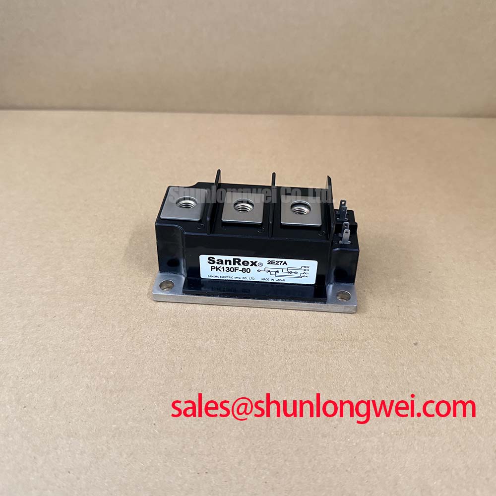
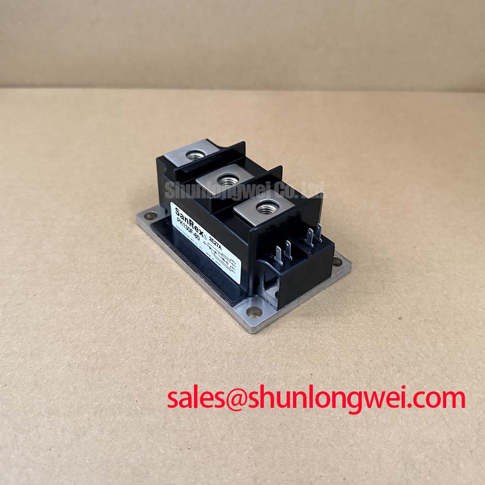
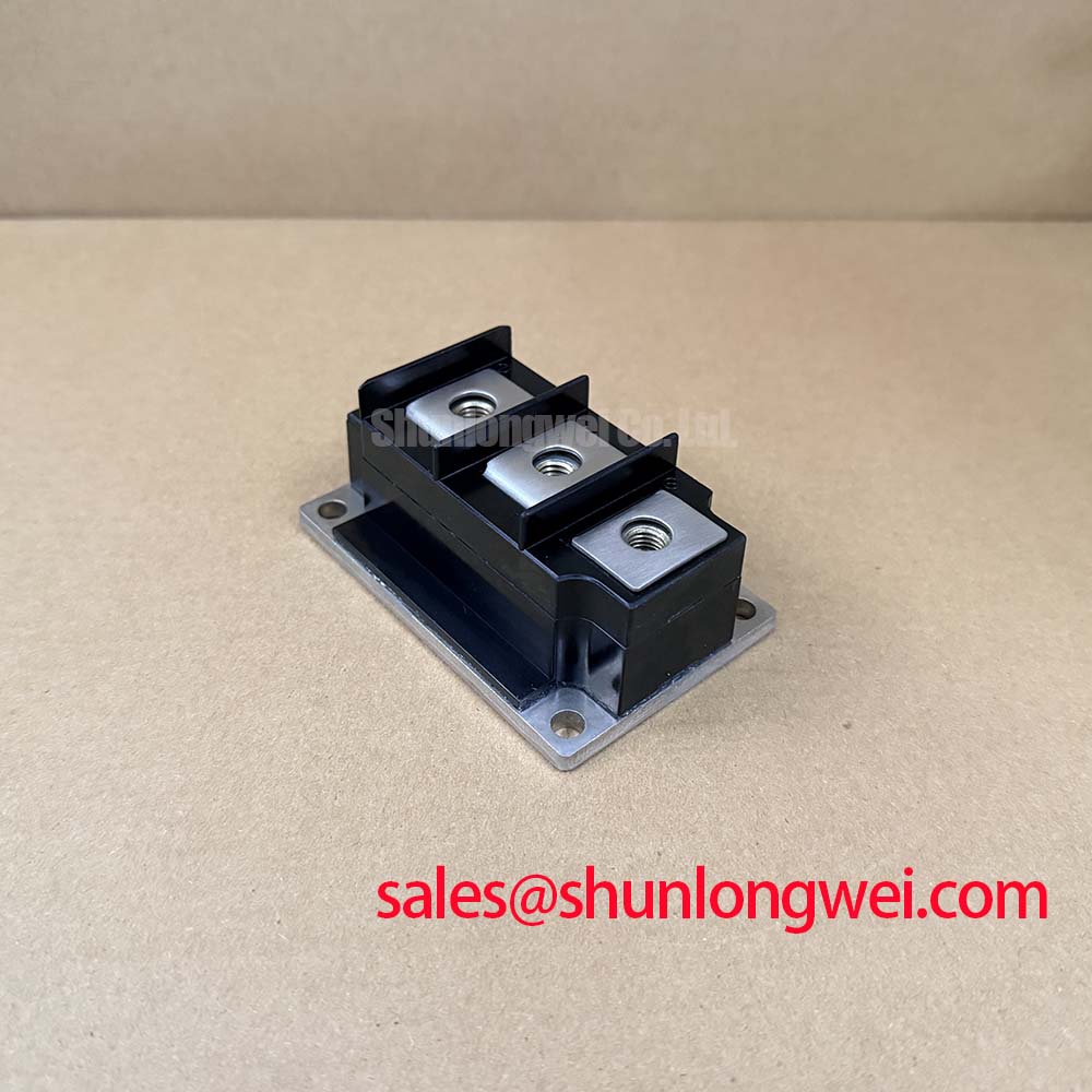
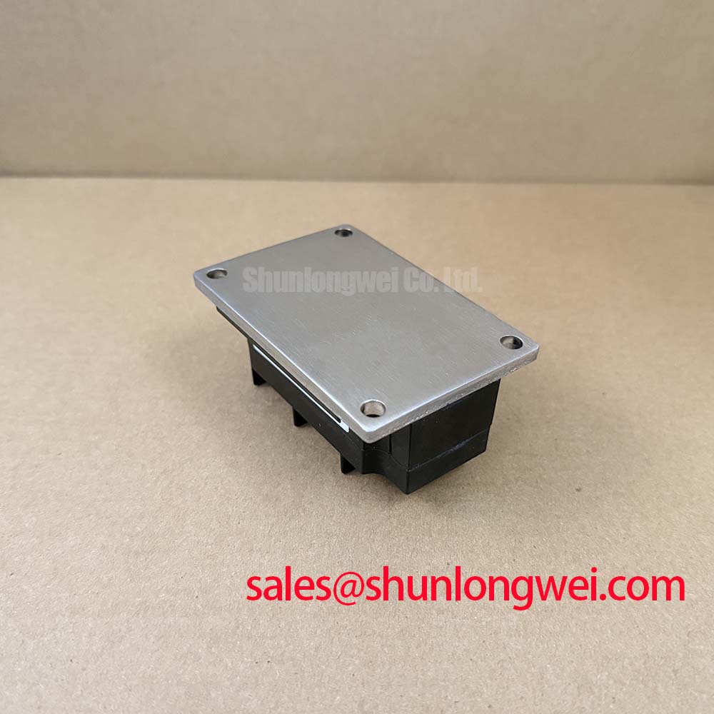
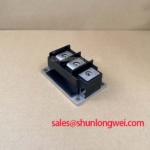
PK130F-80 SanRex 800V 130A Thyristor Diode Module
Begin a replacement assessment by checking the PK130F-80 nameplate, inspecting the case and terminals for physical damage, and confirming that the circuit application matches an 800 V SanRex thyristor and diode module. Before any energized test, isolate the power stage and compare the original wiring, gate connections, heatsink contact, and protective components with the equipment documentation.
The PK130F-80 is specified for high-current controlled rectification and power conversion duties where repetitive voltage, surge current, thermal impedance, and isolation performance must be evaluated together. The published electrical ratings include an average on-state current of 130 A at Tc = 83°C, an RMS on-state current of 205 A, and a non-repetitive surge on-state current of 4400 A at 60 Hz for one cycle. These figures are official specification values, not a guarantee of a particular system operating point.
| Manufacturer | SanRex |
| Product model | PK130F-80 |
| Product category | Thyristor / Diode Module |
| VDRM | 800 V repetitive peak off-state voltage |
| VRRM | 800 V repetitive peak reverse voltage |
| VRSM | 960 V non-repetitive peak reverse voltage |
| IT(AV) | 130 A at Tc = 83°C |
| IT(RMS) | 205 A |
| ITSM | 4400 A, 60 Hz, one cycle |
| Critical dv/dt | 500 V/µs at Tj = 125°C |
| Critical di/dt | 200 A/µs |
| VTM | Maximum 1.40 V at IT = 400 A and Tj = 25°C |
| Rth(j-c) | Maximum 0.20°C/W per SCR element |
| VISO | 2500 V AC for one minute |
PK130F-80 Circuit Protection & Reliability: Calibrating IEEE 61000-4-5 Industrial Surge Immunity
For an AC input stage, protection should be assessed from the incoming line toward the semiconductor terminals. A metal oxide varistor, line impedance, fusing, and RC snubber network each address a different part of the transient problem. The PK130F-80 has an official repetitive peak off-state voltage rating of 800 V and a repetitive peak reverse voltage rating of 800 V; the selected surge protection must therefore be evaluated against the complete switching waveform rather than the nominal supply alone.
IEEE 61000-4-5 is a system-level surge immunity test method. The module itself should not be described as independently certified to that standard. When the equipment is tested, the engineering team should verify the voltage appearing at the thyristor junction after the protective network, wiring inductance, and source impedance have been included. MOV selection is a system design consideration: its clamping behavior, energy capability, standby leakage, and failure coordination should be checked against the actual line arrangement.
Fuse coordination also requires the manufacturer’s published I²t information and the clearing behavior of the selected fuse. The available PK130F-80 data identifies the 4400 A ITSM rating for 60 Hz and one cycle, but a single surge-current value does not replace an I²t coordination table. Designers should obtain the applicable SanRex curves or application data before treating a fuse as adequate for fault protection.
Terminal identification, polarity, gate wiring, and the permitted mounting arrangement must be verified from the original mechanical drawing. Do not infer terminal positions from another package family. The SanRex technical resource at SanRex Sansha Electric Power Semiconductor Modules is the appropriate manufacturer reference for confirming device documentation and application boundaries.
Preventing Spurious Faults: Turn-On Current Rise Limiting for PK130F-80
The official critical off-state voltage rise rate for the PK130F-80 is 500 V/µs at Tj = 125°C, while the critical on-state current rise rate is 200 A/µs. These values define important switching boundaries for the SCR element. They do not prescribe an RC snubber value or a saturable-reactor specification for every converter. The final network depends on line impedance, commutation conditions, gate-drive timing, load behavior, and measured switching waveforms.
In a controlled rectifier or medium-frequency induction power supply, the snubber should be placed with a short, low-inductance connection across the relevant power terminals. The resistor limits capacitor discharge current and damping must be checked during repetitive operation. A series reactor can moderate the current front during turn-on, but its saturation behavior should be assessed at the intended load current so that it does not create an unwanted voltage excursion during commutation.
The gate circuit deserves the same attention as the power path. Keep the gate return physically separated from high-current commutation paths where the package layout permits, and check common-mode ground movement during switching. A negative gate-cathode bias during the off-state is not an official PK130F-80 rating supplied here; if the driver uses one, the integrator should verify the allowable gate-cathode conditions from the complete SanRex gate-drive documentation. Oscilloscope measurements should compare gate voltage, anode-to-cathode voltage, and load current during both normal turn-on and abnormal commutation.
For a replacement decision, the PD104VT2T1 may be reviewed as a direct replacement candidate only after electrical rating, terminal arrangement, thermal interface, gate characteristics, and mounting compatibility have been verified against the original assembly. A similar current or voltage label alone is not sufficient evidence of interchangeability.
💡 Pro Tip: Keep the high-current busbar path physically symmetrical where possible and confirm turn-off overshoot with a properly rated differential probe during a controlled switching test.
PK130F-80 Operational Boundaries: Evaluating Thermal Interface Material Spreading Across Limits
The published maximum junction-to-case thermal impedance is 0.20°C/W per SCR element. This value is an official device specification under its stated test conditions; it is not the thermal resistance of the complete assembly. Heatsink flatness, contact pressure, thermal interface material, mounting hardware, airflow, current waveform, and ambient temperature all affect the resulting junction temperature.
During installation, clean both mating surfaces according to the equipment maintenance procedure and apply the interface material as a uniform, controlled layer. The objective is continuous contact without excessive compound that could increase the mechanical gap or contaminate adjacent insulation. Where a pressure-mounted or spring-loaded heatsink is used, pressure should be distributed evenly across the baseplate. The module should not be forced into alignment by tightening one side before the other.
Exact mounting torque, bolt size, washer arrangement, and any specified spring pressure are mechanical design data that must come from the PK130F-80 drawing or the original equipment manufacturer. They should not be inferred from the electrical current rating. After installation, verify that the heatsink contact is stable, the baseplate is not distorted, and the power terminals are not carrying mechanical stress from rigid busbars.
Thermal validation should use the actual load profile rather than a short no-load test. Measure heatsink temperature at several locations and compare the result with the expected current waveform. The 130 A IT(AV) rating at Tc = 83°C is conditional, so the system engineer must verify case temperature and junction-temperature margin under the intended conduction angle. In a phase-controlled induction furnace, conduction angle, circulating current, and commutation overlap can produce a thermal result that differs substantially from a steady resistive load.
The related PD104SL7 can be considered as a neutral reference when reviewing a complementary rectifier stage, but its electrical and mechanical compatibility must be assessed independently. A paired device should not be assumed interchangeable solely because it appears in the same power topology.
Transient Dynamics & Electrical Design: Reverse Recovery Charge on PK130F-80
Reverse-recovery behavior is important when a thyristor/diode module operates in a commutated bridge, resonant inverter, or medium-frequency induction heating power stage. Recovery charge, peak reverse current, recovery time, and softness influence commutation stress, switching loss, and conducted or radiated noise. The supplied official PK130F-80 parameter set does not specify Irrm, trr, or a quantified soft-recovery class, so those values should be obtained from the applicable SanRex datasheet before detailed loss or EMI calculations are made.
Do not substitute an assumed diode recovery profile for measured data. During a double-pulse or commutation test, monitor the reverse-current peak, voltage overshoot, ringing frequency, and temperature rise while maintaining safe isolation and controlled fault energy. The measured waveform should be compared with the module’s 800 V repetitive voltage boundaries and the equipment’s transient protection response.
Minimize the commutation loop area to reduce parasitic inductance and use an RC or other damping network only after its losses and pulse-current capability have been checked. Long motor or coil cables can behave as transmission-line elements, allowing reflected voltage to increase the stress seen at the switching node. The system designer should select filtering and termination methods from the actual cable impedance and waveform measurements rather than applying a universal filter value.
For phase-controlled rectification, harmonic performance is determined by the complete converter, firing-angle control, source impedance, line reactor, and load. The PK130F-80 data confirms current and voltage capability but does not constitute an EMC or power-quality certification for the finished furnace. Engineers evaluating resonant or quasi-resonant arrangements can consult Resonant Topologies in Home Appliances when comparing system-level current paths and commutation behavior.
Any final safety and qualification review should also reference IEC 60747-6 Semiconductor Devices: Thyristors. Isolation verification remains an assembly-level task: the published 2500 V AC isolation rating for one minute should be interpreted with the module construction, mounting hardware, creepage, clearance, pollution environment, and test procedure all considered.