

Content last revised on September 27, 2026
Benchtop Waveform Tuning: Mitigating Stress via Pulse-Transformer Isolated Firing Circuit on KS524505
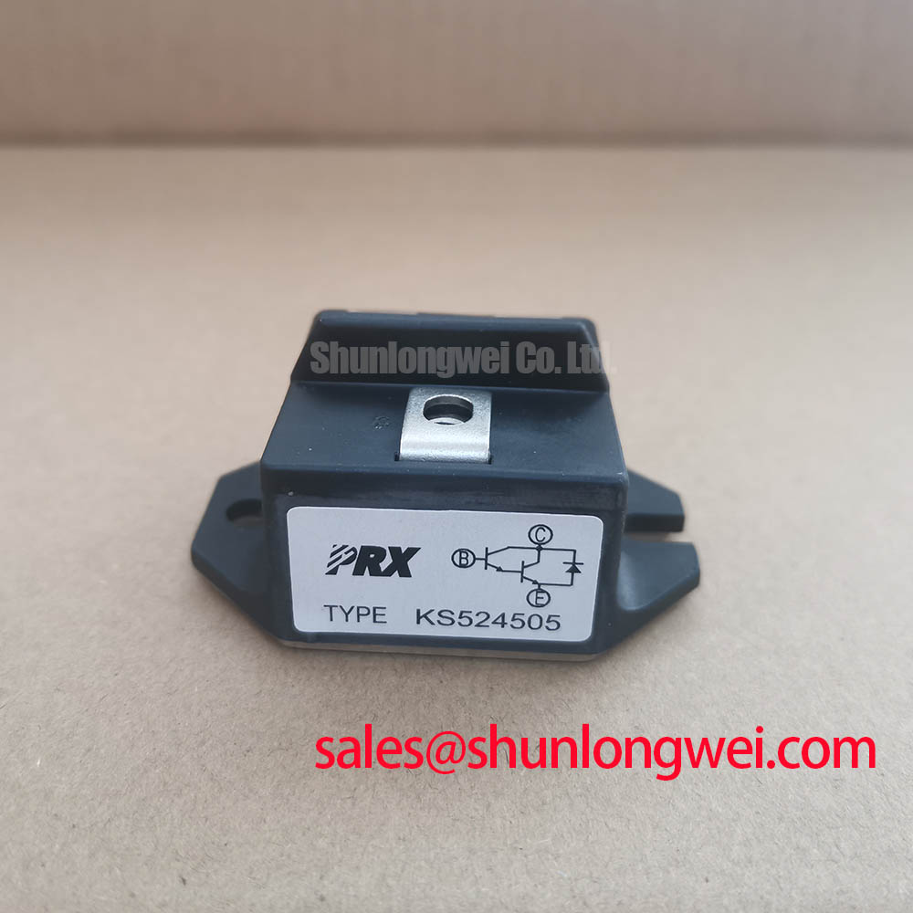
Before energizing the rectifier, compare the KS524505 nameplate with the circuit documentation, then verify terminal identification and mounting requirements against the applicable Powerex drawing. The specified electrical ratings are 4500 V and 520 A, with a POW-R-BLOK package. These ratings identify the component’s nominal electrical class; they do not establish permissible operating conditions without the associated temperature, waveform, cooling, and mounting requirements.
The Powerex KS524505 product page provides the model reference for purchasing and equipment documentation. For thyristor firing-circuit evaluation, the important distinction is between the component’s published ratings and the waveform delivered by the installed driver. A transformer-isolated firing circuit must be assessed at the device terminals, not only at the controller output, because transformer behavior, wiring impedance, and the gate return path can alter the delivered pulse.
| Parameter | Official Specification | Integration boundary |
|---|---|---|
| Model | KS524505 | Match the complete designation to the equipment parts list. |
| Manufacturer | Powerex | Use the applicable manufacturer documentation for detailed limits. |
| Rated voltage | 4500 V | Confirm the corresponding voltage symbol and test conditions before setting operating margins. |
| Rated current | 520 A | Confirm the current definition, waveform, and thermal conditions. |
| Package | POW-R-BLOK | Verify the mechanical drawing, terminal arrangement, and mounting instructions. |
Design Consideration: assess firing-pulse amplitude, leading-edge behavior, duration, and any sustained gate-current portion against the manufacturer’s gate requirements. A repetitive pulse train should be evaluated together with transformer reset and gate power dissipation. Neither a numerical gate-current rise requirement nor a back-porch current can be assigned to KS524505 from its voltage and current ratings alone.
During controlled commissioning, compare gate current with the onset of main-circuit conduction. Delayed or inconsistent conduction warrants inspection of firing synchronization, transformer output, connection integrity, and load conditions before changing pulse strength. Obtain the specified terminal tightening and mounting torque from the applicable drawing; package naming alone does not determine either value.
Preventing Spurious Faults: Turn-On Current Rise Limiting Guidelines for KS524505
Design Consideration: distinguish voltage-rate-induced triggering from commanded turn-on followed by excessive current rise. Both require waveform evidence, but they involve different circuit conditions. Capture the voltage across the device, the relevant branch current, and the gate signal with appropriately rated instrumentation. Review probe placement and reference paths before interpreting ringing as a semiconductor fault.
An RC snubber should be evaluated against the actual commutation waveform, repetitive energy dissipation, and the manufacturer’s voltage-rate limits. Its resistance and capacitance are system-determined values, not consequences of the 4500 V nameplate rating. If the circuit includes a saturable reactor, verify its magnetic reset, load-dependent behavior, and thermal condition against the equipment design rather than treating it as a universal protection accessory.
Design Consideration: minimize and balance commutation-loop inductance to reduce transient voltage stress, then verify the resulting margin with measured waveforms under the intended operating conditions.
Inspect busbar joints, snubber connections, and the physical relationship between the protection network and the power terminals. A sound component can still experience excessive transient stress when the protective network is connected through a long or poorly controlled current path. Where DC-link capacitors are present, Film Capacitors in High Ripple Current DC-Link Applications provides general background on film-capacitor construction and applications; individual capacitor ratings and suitability still require their own manufacturer documentation.
Do not transfer IGBT gate-drive practices directly to a thyristor firing circuit. Miller-platform charge, active gate clamping, and bootstrap supply sizing are not established KS524505 requirements. Any such functions elsewhere in the converter should be assessed against the devices they actually control.
Field Diagnostics & Commissioning: Reverse Recovery Charge Temperature Effects in KS524505 Topologies
Begin recovery-related troubleshooting by identifying which circuit element carries the commutating current. An external rectifier or freewheeling diode needs its own recovery specification; its characteristics cannot be attributed to KS524505 merely because it shares the same assembly. Thyristor turn-off behavior likewise requires the applicable device data and circuit commutation conditions.
Design Consideration: compare recovery-current peaks, voltage overshoot, and ringing across representative load and thermal states. Reverse-recovery charge, recovery time, and softness depend on stated measurement conditions. Without component-specific values and those conditions, assigning a recovery coefficient or numerical softness factor would create an unsupported compatibility claim.
When waveforms differ from a known-good assembly, inspect the commutation path, cooling interfaces, diode documentation, and firing timing before attributing the difference to one component. Use repeatable probe positions and comparable operating conditions. A cold impedance check can identify connection anomalies, but it cannot establish recovery performance under power.
The broader discussion in The 1200 V CoolSiC™ MOSFET Advantage in Three-Phase Power Conversion offers context for switching-loop and commutation considerations. Its SiC-specific characteristics are not KS524505 specifications and should not be used as replacement criteria.
For a high-current green hydrogen electrolyzer DC power rectifier, compatibility assessment should include the bridge arrangement, commutation conditions, cooling system, firing controller, and mechanical interface. The listed voltage and current ratings are screening information, not proof of suitability for that equipment.
KS524505 Circuit Protection & Reliability: Coordinating Short-Circuit Withstand Limits
Semiconductor fuse coordination requires more than matching the fuse current rating to 520 A. Obtain the KS524505 surge-current and withstand data, including their waveform and temperature conditions, alongside the fuse manufacturer’s pre-arcing and total-clearing characteristics. The supplied electrical and package specifications do not establish a device I²t limit or a coordinated fuse selection.
Design Consideration: compare fuse let-through energy with the semiconductor withstand boundary under compatible conditions, while accounting for prospective fault current, circuit voltage, and interruption behavior. A lower energy figure alone does not establish protection if the compared values use different conditions. Coordination also needs review of the enclosure, conductors, and upstream protective devices.
Do not equate a thyristor surge rating with an IGBT short-circuit withstand interval. Nor can fuse coordination guarantee damage-free interruption of every fault. The responsible system engineer should validate the protection arrangement using manufacturer coordination information and the equipment’s fault assessment.
Before approving a replacement, retain the terminal drawing, specified mounting procedure, thermal-interface requirements, firing-waveform records, and fuse coordination documentation with the equipment service file. If a required limit is unavailable, obtain it before powered validation rather than substituting a generic torque, gate setting, or withstand value.