

Content last revised on September 11, 2026
Optical Luminance Degradation Curve and CCFL to LED Modernization Retrofit Pathways
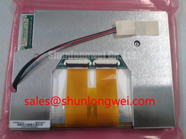
Verify the original panel identification, connector orientation, backlight arrangement, and mechanical opening before applying power to a replacement PD050VL1. The available factory context identifies this unit as a PVI (Prime View International) Industrial Grade LCD/HMI Panel in a TFT-LCD Display Module package, with its specification status recorded as Official Factory Spec Verified. The supplied factory data does not confirm the panel resolution, interface type, logic supply voltage, backlight technology, luminance, viewing angle, response time, or outline dimensions, so those values should be checked against the original panel documentation and equipment service records.
For a failed display in an AGV or forklift telematics console, begin by separating the image-generation fault from the illumination fault. A panel that produces a visible image under controlled inspection but lacks usable brightness requires a backlight investigation, while a completely inactive screen also requires checks of the logic supply, signal path, connector seating, and host controller. The PD050VL1 factory context supplied here does not identify whether the original backlight is CCFL or LED. The system integrator should verify the required backlight architecture from the original panel documentation rather than assuming a modernization path.
When a CCFL assembly is confirmed, cold ignition involves a high-voltage inverter and requires suitable isolation, wiring clearance, and an approved test procedure. The often-cited ignition range of 1500 to 1650 Vrms is not an official PD050VL1 specification in the supplied data and must not be treated as a module rating. A replacement LED assembly also cannot be selected solely by physical fit. Its forward-voltage range, current regulation method, dimming input, connector pinout, optical coupling, and thermal behavior must match the display system.
A constant-current LED driver may support PWM dimming, but a 1000:1 dimming ratio is not verified for this model. It should therefore be treated as a driver capability to confirm, not as a performance claim for the PVI panel. During retrofit evaluation, engineers should inspect brightness uniformity across the active area, startup behavior, electromagnetic noise from the driver, and interaction with the host controller’s enable signal. Claims concerning a 50,000-hour half-life or MTBF also require a manufacturer reliability document for the complete backlight assembly; they cannot be assigned to the PD050VL1 from the available factory information.
Fuse coordination belongs to the complete display power branch rather than to the panel category alone. The correct fuse type, interrupt rating, and I²t relationship depend on the actual supply architecture and measured inrush current. No PD050VL1 fuse I²t table was supplied, so the equipment designer should obtain the original circuit documentation and validate protection through controlled testing. Terminal connections should be compared pin by pin with the removed unit, including power return, enable, dimming, signal ground, and any unused terminals.
💡 Pro Tip: Disconnect power and allow the display assembly to discharge before removing a backlight or signal connector, then document connector orientation with a photograph before reassembly.
Thermal Cycling Degradation of Polarizer Adhesives and Sealant Gasket Integrity
The product data supplied for PD050VL1 confirms the product category and package style but does not publish an operating temperature range, storage temperature range, humidity rating, polarizer adhesive specification, or perimeter sealant construction. The proposed cycle of −30°C to +85°C is therefore not an official rating for this display. It may be used only as a system-level qualification condition when required by the equipment specification and when confirmed against the panel’s original documentation.
In cold operation, liquid-crystal response can become slower, and image transitions may appear less responsive. That observation alone does not establish a failed panel. Engineers should compare gray-to-gray behavior at the intended operating temperature, inspect for image retention after stabilization, and verify whether the host timing controller is maintaining the required frame and synchronization signals. If the panel is installed behind a protective window, the enclosure and window can also affect heat retention, condensation, and optical contrast.
Perimeter gasket and sealant evaluation should focus on visible separation, pressure marks, moisture traces, and changes in the bezel fit after thermal exposure. The available specification context does not confirm an epoxy sealant type or a specific ingress-protection level. Designers should therefore treat enclosure sealing as a system responsibility and validate it with the actual front bezel, cable exits, mounting frame, and cleaning procedure used in the vehicle display.
Mechanical stress is particularly important when a replacement panel is clamped into a rugged telematics housing. Uneven fastener loading or a distorted opening can transfer force into the glass and produce localized contrast changes, edge discoloration, or intermittent behavior during vibration. The appropriate mounting torque is not published for PD050VL1. Use the original equipment service specification where available; otherwise, the integrator should establish a controlled assembly method through fit and vibration testing rather than assigning an unverified torque value.
For broader enclosure and HMI reliability considerations, engineers can consult the Industrial Display and HMI Solutions engineering resource. It should supplement, not replace, the specific PVI panel documentation and the vehicle manufacturer’s environmental requirements.
Diffuser Film and Prism Sheet Thermal Buckling Prevention under Continuous Full Duty Operation
Optical films, diffuser layers, and prism structures should not be presumed from the product category alone. The supplied PD050VL1 information does not confirm the internal optical stack, diffuser material, prism-sheet design, LED arrangement, or thermal derating curve. Consequently, statements about PMMA yellowing, L70/B50 life, or a particular optical film construction would require a dedicated backlight datasheet or reliability report.
For continuous operation, inspect the assembled panel for brightness gradients, edge hot spots, color shift, and changes in illumination after the unit reaches thermal equilibrium. A narrow aluminum heat spreader rail may be considered when the enclosure design shows a localized heat source near the display edge, but its thickness, attachment method, and thermal path must be determined by the system engineer. The rail must not obstruct the active area, apply point pressure to the panel, or interfere with the backlight connector and cable bend radius.
Thermal measurements should be made at the backlight driver, connector region, bezel, and display edges while the unit operates in its intended brightness mode. A thermal camera can reveal distribution, but surface emissivity and reflective metal parts can affect readings. Where a display is installed in an AGV or forklift console, vibration testing should be performed after thermal testing because repeated movement can change film seating, connector contact, or bezel compression.
Power electronics located near the display can introduce both heat and conducted noise. SanRex information on power semiconductor modules and ROHM information on fast recovery diodes may help engineers review adjacent converter hardware, switching behavior, and suppression choices. These external references do not establish the electrical, optical, thermal, or reliability ratings of the PD050VL1 itself.
When a visually similar panel is evaluated as a neutral replacement candidate, compare the active-area position, connector location, mounting-hole pattern, thickness, optical direction, and host interface before approving the change. The KCS057QV1AA-G01 may be reviewed as a separate same-class display option, but compatibility must be demonstrated by documentation and physical testing rather than inferred from product category or appearance.
Logic Supply Voltage Sequencing and Driver IC Latch Up Risk Control
The available factory parameters do not specify whether PD050VL1 uses a TTL or LVDS input, whether its logic supply is 3.3 V or 5.0 V, which pixel mapping is used, or what power-on timing limits apply. The system integrator should verify the required supply voltage from the original panel documentation. Applying an assumed voltage or connector pinout can damage the panel electronics or create an apparently intermittent service fault.
Before connecting a replacement unit, identify every connector contact from the original wiring diagram. Separate logic power, return, display data, clock or synchronization lines, backlight control, and shield or chassis connections. If the equipment uses LVDS, verify the differential pair assignment, polarity, termination arrangement, and host serializer format. If it uses TTL, confirm the number of data bits, clock edge, synchronization signals, and voltage levels. The terms JEIDA and VESA describe possible data mappings, not a confirmed PD050VL1 interface specification.
Power sequencing should be checked with an oscilloscope at the panel connector while the host system starts and stops. The proposed rise-time window of 0.5 ms to 10 ms is not published in the supplied PD050VL1 factory data. It should not be used as a model-specific limit unless confirmed by the original datasheet. Engineers should instead compare the measured sequence with the controller documentation, ensuring that data activity, enable signals, and logic power appear in the order required by the complete assembly.
For LVDS routing, maintain a continuous reference plane, avoid unnecessary stubs, and control pair symmetry through the connector transition. A 100-ohm differential characteristic impedance is a common LVDS design target, but it is not confirmed as a PD050VL1 factory parameter. The board designer should verify the host transceiver standard and transmission-line requirements before selecting a routing target. Split-screen images, unstable synchronization, or colored vertical regions may indicate a mapping, polarity, timing, connector, or signal-integrity issue; compare the suspect path with a known-good signal using suitable probing rather than assigning a single cause.
The final integration check should cover the display cutout, bezel compression, cable strain relief, backlight control, supply behavior, and image format under vibration and temperature conditions required by the equipment. For procurement and repair records, identify the unit as a PVI PD050VL1 Industrial Grade LCD/HMI Panel and retain the original equipment documentation that confirms the missing electrical and mechanical parameters.