

Content last revised on October 6, 2026
Incoming Inspection of the LM150X07 LCD Panel
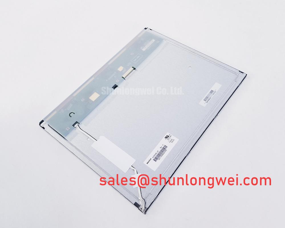
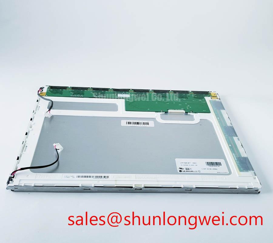
Begin the bench check by confirming the LM150X07 identification, inspecting the panel surface under controlled illumination, and verifying that the controller interface matches the original equipment documentation before applying power. This LG Display panel is a 15.0 inch diagonal a-Si TFT-LCD with a 1024 × 768 XGA active resolution, a 4:3 format, and a 60 pin TTL interface with 2 channels and 6-bit data.
The official supply specification identifies 5.0 V typical VDD. The system integrator should verify the required voltage and power sequencing from the original panel documentation rather than assuming compatibility from connector appearance alone. A 60 pin TTL panel should not be connected to an LVDS-only controller without a verified interface solution, and this model should not be described as a native LVDS display.
| Specification | LM150X07 Official Specification |
| Manufacturer | LG Display |
| Display type | 15.0 inch diagonal a-Si TFT-LCD |
| Active resolution | 1024 × 768 pixels, XGA |
| Signal interface | TTL, 2 channels, 6-bit, 60 pins |
| Supply voltage | 5.0 V typical VDD |
| Typical luminance | 250 cd/m² |
| Typical contrast ratio | 350:1 |
| Backlight | 2 pcs CCFL, edge-light type |
| Backlight lifecycle | 40,000 hours minimum operational lifecycle |
| Surface finish | Antiglare, hard coating, 3H |
For incoming optical inspection, display full red, green, blue, white, black, and neutral gray test screens. Record any fixed bright point, dark point, discolored pixel, vertical line, horizontal line, or uneven illumination while viewing the panel from a consistent position. The 250 cd/m² typical luminance and 350:1 typical contrast ratio are official typical values, not a substitute for a system-level acceptance limit established by the equipment manufacturer.
💡 Bench Tip: Keep the panel and controller connected to an ESD-safe work surface, and confirm that the 60 pin cable is fully aligned and locked before energizing the display.
Single Vertical Hairline Defect and Column Driver Localization
A single vertical hairline defect should first be documented on each primary color screen and on a full white field. If the line remains fixed at the same column position across several test images, the observation may be associated with the panel signal path, column addressing, or a connection issue; it should not be assigned to one internal cause without comparative testing. Check the cable seating, connector lock, controller output, and a known-good display path where available.
A 45-degree flashlight inspection with the backlight disabled can help separate an image-data defect from an illumination defect. A line that remains visible as a dark image feature during reflected-light inspection deserves a different investigation from a region that disappears when the CCFL illumination is removed. This is a practical localization method, not a replacement for panel-level electrical analysis.
The LM150X07 uses an edge-light arrangement with 2 pcs CCFL. A dim section, uneven edge glow, or intermittent illumination should therefore be checked through the backlight wiring and inverter system as well as through the display image path. The official panel data identifies the backlight type and a 40,000-hour minimum operational lifecycle; it does not establish a universal field failure rate or guarantee uniform performance after installation in a particular enclosure.
Cold operation requires separate attention. At sub-zero ambient temperatures, liquid-crystal response can become slower, so a moving graphic or gray transition may appear delayed during equipment start-up. This condition should be assessed using a repeatable warm-up sequence and the actual enclosure temperature. If a heater strip is present in the equipment, its control method, location, and thermal limit remain system design matters. The panel documentation supplied for this product does not provide a universal heater setting or a guaranteed response-time value for every cold environment.
For equipment such as a heavy mining shovel or earthmoving telematics display, inspect the bezel, mounting points, cable bend path, and protective window together. Mechanical vibration can disturb a marginal connector or create intermittent image behavior without producing a permanent visible defect. The Industrial Display and HMI Solutions engineering guide provides broader design context for industrial display integration, while final acceptance should be based on the original equipment test procedure.
Pixel Jitter and Horizontal Noise Near 400 V Motor Drives
When pixel jitter or horizontal white bands appear near a 400 V variable-frequency motor drive, begin by comparing the display with the drive disabled, the machine operating at different load conditions, and the controller connected through its normal cable route. This comparison can indicate whether the disturbance is related to conducted or radiated coupling, grounding, cable routing, or timing integrity. It does not prove that the panel itself is defective.
The LM150X07 uses TTL signaling through a 60 pin interface, so the cable arrangement and controller pin mapping must be confirmed against the original documentation. Do not substitute an LVDS cable or assume that a visually similar connector carries the same signal assignment. Keep high-energy motor-drive conductors physically separated from the display cable where the equipment layout permits, and avoid routing the signal harness parallel to switching conductors for long distances.
A shielded cable may be evaluated where the system requires additional noise control. Shield termination, chassis bonding, and signal reference strategy should be selected by the system engineer after reviewing the enclosure and grounding architecture. A ferrite component can also be considered as a common-mode suppression measure, but its effectiveness depends on impedance characteristics, placement, cable construction, and the frequency content of the disturbance. These are design considerations rather than official LM150X07 electrical specifications.
Use an oscilloscope at the controller output and, where safely accessible, at the display-side signal entry to compare the known-good and disturbed conditions. Observe the signal reference, clock relationship, and transitions while the motor drive changes state. The investigation should also include the panel supply rails, because supply disturbance can resemble a data integrity problem. Keep probing non-invasive and follow the equipment manufacturer’s isolation and high-voltage safety procedures.
The antiglare hard coating with a 3H surface hardness rating helps with routine surface abrasion and reflections, but it does not provide immunity from electrical noise, vibration, or impact. A protective window, sealing method, and enclosure grounding scheme should be evaluated at the equipment level. The display component itself should not be represented as independently certified for whole-machine EMC compliance.
Cold-Start Gray-to-Gray Response Evaluation
Evaluate gray-to-gray behavior by applying the same image sequence at room temperature and during the actual cold-start profile of the machine. A change in transition speed at low temperature can result from temperature-dependent liquid-crystal behavior, controller timing, backlight warm-up, or the surrounding mechanical assembly. Use a photodetector or high-speed camera when numerical response characterization is required, and compare the result with the equipment acceptance criteria.
The official data provided for the LM150X07 confirms the display format, interface, luminance, contrast, and CCFL backlight arrangement, but it does not establish a universal GTG response-time figure across the entire operating range. Do not convert a visual cold-start delay into a fixed panel failure diagnosis. Check the controller timing, supply stability, image content, and enclosure temperature before deciding whether replacement is necessary.
For installations exposed to repeated cold and warm cycles, designers should inspect the panel frame, mounting pressure, cable strain, and perimeter sealing arrangement after environmental testing. The purpose is to identify visible stress, connector movement, or optical changes without inventing an internal material specification that is not provided by the manufacturer. Sealants, gaskets, and heater controls should be selected and qualified by the equipment designer for the intended enclosure.
The 250 cd/m² typical luminance is useful for judging indoor factory control-room visibility, but perceived brightness in an outdoor or open-cab machine depends on the viewing window, ambient light, glare, and optical stack. For a telematics display in heavy earthmoving equipment, engineers should confirm that the existing bezel and cover allow sufficient viewing contrast without applying unverified claims about sunlight readability.
Backlight service work also requires a complete system check. Since this model uses CCFL rather than an LED backlight according to the supplied specification, the original inverter, lamp wiring, and safety interlocks must be verified before commissioning. The replacement process should follow the equipment service manual, with particular attention to connector seating and insulation clearance. The panel’s stated backlight lifecycle is a component specification and should not be presented as a guaranteed machine operating lifetime.
TTL Timing, Pixel Clock, and Cable Compatibility
Confirm the controller timing and pin assignment from the original LM150X07 documentation before connecting the replacement panel. This model has a 60 pin TTL interface with 2 channels and 6-bit data; it is not specified here as a 20 pin or 30 pin LVDS panel. A controller that uses differential LVDS signaling, JEIDA mapping, or VESA mapping requires a separately verified interface path and should not be connected by relying on pin-count similarity.
During commissioning, verify the controller’s logic supply requirement, power-on sequence, pixel clock, sync signals, and data mapping against the panel documentation. The supplied product specification confirms 5.0 V typical VDD, while the actual controller implementation, tolerance, rise behavior, and reset sequence must be checked in the original equipment. The system integrator should verify the required supply voltage from the original panel documentation.
Split-screen artifacts, unstable text, missing color bits, or a shifted image may indicate an interface mapping or timing mismatch. Trace the signal path from the controller to the 60 pin cable, confirm connector orientation, and compare the observed waveform with a known-good unit. Use controlled changes so that cable seating, timing settings, and power conditions are not altered simultaneously.
Signal integrity is also affected by cable length, return path, connector condition, and routing beside switching power hardware. Minimize unnecessary loop area and maintain a clear reference path to reduce susceptibility to coupled noise; the final routing and termination arrangement should be verified by the system engineer during switching tests. A PWM frequency or duty-cycle value for backlight control should not be assigned to this panel without confirmed documentation, especially because the specified backlight is CCFL rather than an integrated LED current-drive system.
Before release to service, repeat the full-color pixel inspection, black-field uniformity check, brightness comparison, cable movement check, and cold-start evaluation. Record the panel identification, controller used, supply condition, visible defects, and test temperature. This creates a useful incoming-QA record for industrial HMI repair without treating a single observation as conclusive evidence of an internal failure.