

Content last revised on October 7, 2026
Display Edge Heat and Light Guide Preservation
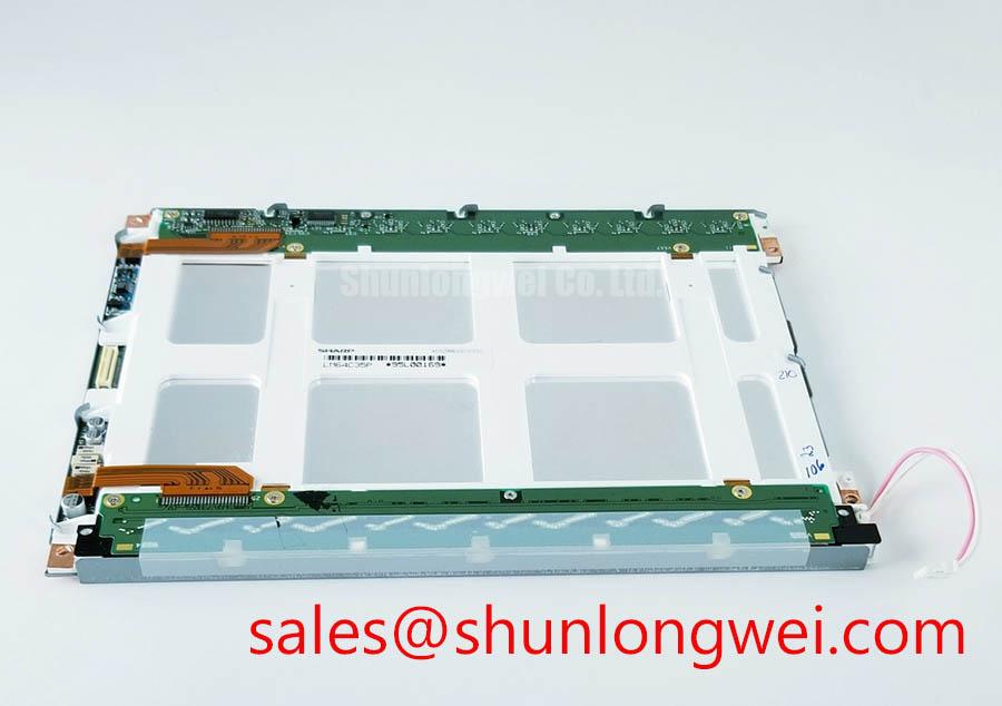
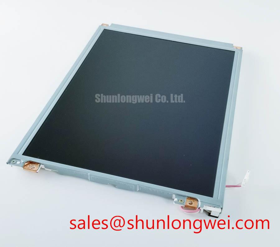
With the console power isolated, compare the installed display label with Sharp LM64C35P, then photograph the cable routing and connector orientation before removing the panel. The LM64C35P is an LCD display module. That identity is a starting point for a repair assessment, not evidence that another panel, backlight supply, or signal cable will fit.
In a marine radar or navigation bridge console, sunlight, enclosure heat, and long operating periods can expose a display assembly to uneven temperatures. Inspect the LM64C35P mounting edges for blocked ventilation, displaced padding, and pressure marks before attributing a bright or dim region to the LCD itself. If the surrounding assembly has a separate backlight driver or heat spreader, record its part number and attachment points. The available LM64C35P product information does not establish the backlight technology, light guide material, edge rail dimensions, or a rated backlight lifetime.
Design Consideration: thermal changes should be assessed at the assembled-console level. Compare the appearance of a uniform test image after a cold start and after normal warm-up, while recording ambient conditions and any local heating near the display edges. A persistent bright band may warrant inspection of mechanical pressure and illumination before a panel fault is assumed. Any change to heat spreading or ventilation should be evaluated against the original console design rather than treated as a modification specified by Sharp for this module.
Salt-laden air and cleaning residue also make the enclosure boundary important. Examine the front gasket for flattening, gaps, or contamination, and check whether the cover closes evenly around the display. Optical bonding and a sealed front surface cannot be inferred from the LM64C35P model name. If moisture appears behind the viewing window, identify which surface carries the condensation before disturbing the panel assembly; the remedy may lie at the enclosure seal rather than in the LCD.
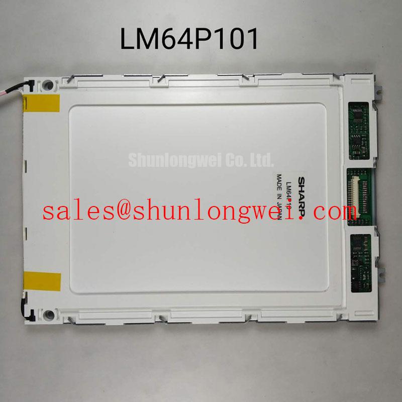
For a panel comparison, LM64P10 can be reviewed as a separate reference model. Treat it as a comparison, not a confirmed replacement. Match the original mechanical drawing, active area, connector assignment, supply requirements, video timing, and backlight arrangement before making a compatibility decision.
Backlight Supply and Power Sequence Checks
A blank or briefly white screen calls for measurements at the installed assembly, not an assumption about its lamp type. Trace the backlight supply and display power paths from the console schematic, then identify which signals are present when the fault occurs. The available LM64C35P product information does not specify a CCFL striking voltage, an LED driver, a dimming method, or a backlight endurance rating. Applying a supply selected from another display’s documentation would therefore be unsafe as a diagnostic shortcut.
Power sequencing matters because an LCD can appear lit while valid image data is absent. During a controlled restart, observe whether the host supply, panel supply, image signals, and backlight enable arrive in the order required by the original equipment documentation. If the screen remains white, compare those observations with a known-good console or the equipment schematic before assigning blame to the module. For an afterimage that persists during shutdown, check how the host removes image drive and panel power; do not prescribe a discharge circuit without the applicable interface requirements.
Design Consideration: on a vibration-prone bridge console, inspect the backlight and signal connectors for movement, cable strain, and contact contamination. A flicker that changes when the enclosure is moved may justify connector and harness checks, but it does not prove a particular internal panel failure. Keep probe placement and isolation appropriate to the identified circuit, especially when the original equipment contains a separate high-voltage backlight supply.
Maintenance Note: Isolate power before reseating display cables, and inspect vibration pads for displacement before closing the console.
Viewing Performance Under Bridge Lighting and Temperature Changes
Assess the LM64C35P from the operator’s normal viewing position with the console’s actual cover glass in place. Reflections from daylight, fingerprints, and residue on that glass can obscure fine radar or navigation details even when the LCD produces a stable image. Clean only with a method approved for the installed front surface, and compare the displayed image before and after cleaning. The available product information does not identify a viewing-angle technology, anti-glare treatment, contrast specification, or rated temperature range for this model.
Where image appearance changes with temperature, record the conditions and allow the assembled console to stabilize before repeating the test. Compare a uniform image and a familiar equipment screen at the same viewing angle. This separates a repeatable display behavior from a change caused by viewing position, cover-glass reflections, or condensation. Claims of a particular liquid-crystal mode or symmetric viewing cone require model-specific documentation and should not be used to approve an installation.
Long periods on a static HMI page deserve a practical check as well. If a previous screen remains faintly visible after the image changes, note how long the page was displayed, whether the effect clears, and whether it appears across different test images. Review any screen-management options provided by the host equipment without assuming a specified image-retention limit for the LM64C35P.
Before moving this module into a different console, obtain the original panel and host interface documentation. Connector shape alone does not establish signal compatibility; supply rails, pin assignments, timing, and any differential signaling requirements must be checked against the actual design. No trace impedance or skew budget is confirmed here for the LM64C35P.
Locating a Single Vertical Line or Uneven Illumination
Begin a line-defect assessment with full-screen test images from a known-good video source. Record whether the line stays in the same position on each image, changes with the source, or disappears when a different test pattern is shown. Then check the signal cable seating and compare the host output with a known-good signal path where the equipment permits. A fixed hairline is useful evidence, but it does not by itself identify an open column driver or a specific internal construction fault.
Next, inspect a dark test image in subdued ambient light and illuminate the front surface obliquely with a flashlight. A mark that moves with the light angle may be on the cover glass or an accessible surface; a fixed bright or dark area may require further separation of illumination, image-drive, and mechanical-pressure effects. Avoid pressing on the active display area to reproduce the symptom. Document the test image, viewing angle, and whether the defect is visible before and after the console warms up.
If the display is uniformly dark, distinguish an absent image from absent illumination using the equipment’s approved test procedure. If an image is faintly visible under external light, examine the backlight power and enable path. If no image is discernible, continue with supply and signal checks rather than replacing the backlight on appearance alone.
Before refitting the LM64C35P, remove loose debris from the mounting area, confirm that the gasket and vibration supports sit where the console drawing specifies, and route cables without pinching them behind the frame. Use the original equipment’s fastening instructions; no LM64C35P-specific mounting torque is established by the available product information. Recheck the test patterns and the normal navigation display after the enclosure is closed, since frame pressure or cable movement can change a symptom that was absent on the bench.