Content last revised on October 20, 2026
Micro-Twist Mechanical Stress Fracture Prevention on Glass Substrate Driver Bumps
When a panel shows intermittent lines, partial color loss, or a dark region that changes as the bezel is pressed, begin with mechanical isolation rather than immediately replacing the controller. A controlled primary-color test helps identify whether the defect follows the image data or remains fixed in the optical area. Use red, green, blue, white, and black screens at a stable brightness level, then inspect the panel obliquely with a flashlight positioned around forty-five degrees to the viewing surface. A fixed dark shadow can point toward the illumination path, while a narrow line or color-dependent discontinuity may require closer inspection of the glass edge and bonded driver region.
Do not twist the glass while inserting the module into an open-frame chassis. Support the panel evenly, keep cable routing free from tensile load, and prevent the bezel from contacting active viewing areas. A panel that passes bench testing can still develop a line defect if the chassis introduces local flex during final fastening. The enclosure designer should determine the required clearance from the panel outline and validate the result by repeating the color-pattern test after assembly.
For high-noise equipment, differential signal routing should preserve the interface topology used by the original display system. Maintain matched trace geometry, avoid unnecessary stubs, and keep the display cable away from fast-switching power conductors. The stated differential impedance and skew targets, if applicable to the host interface, belong to the system interconnect design rather than being treated as an inherent rating of this display module. Verify the eye opening and signal quality at the receiving interface with the installed cable and controller.
For a service replacement with a related display format, engineers may also evaluate LQ10D421 as a separate compatibility candidate. Connector position, image timing, active area, and mounting geometry must be compared before procurement approval.
Constant Luminance Output Control and LED Half-Life Verification
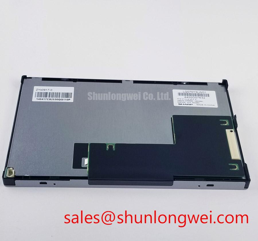
Uneven brightness should first be divided into two test paths: optical illumination and image generation. A uniform white field reveals broad luminance variation, while a black field can expose light leakage, edge glow, or localized bright regions. If the image remains correct but the panel is visibly dim, inspect the host backlight driver, enable signal, current regulation, and protection status. The system integrator should verify whether the installed LQ070Y5DG06 assembly uses the same backlight arrangement as the original equipment rather than assuming a replacement driver or light source is interchangeable.
Thermal inspection is useful when brightness changes after warm-up. Look for localized heat near the narrow display edges, connector region, and backlight driver components. A chassis heat spreader may be considered where the enclosure creates a concentrated thermal zone, but its dimensions, contact pressure, electrical isolation, and thermal path must be determined by the equipment designer. Avoid pressing a metal rail directly against the glass or optical stack.
Claims about LED half-life, L70 or B50 performance, MTBF, sunlight contrast, and anti-glare or anti-reflective treatment should be matched to the applicable panel documentation and the complete display assembly. Those values are not established by the decoded product category alone. In a marine radar or navigation console, direct sunlight, salt-laden air, condensation, and enclosure reflections can change the visible result even when the panel is functioning electrically.
Sharp’s Industrial Display Solutions resources provide useful manufacturer-side context for display integration and optical evaluation. They should be considered alongside the equipment maker’s original display specification when assessing viewing conditions.
Flush-Mount Open-Frame Bezel Integration and Perimeter Gasket Shock Isolation
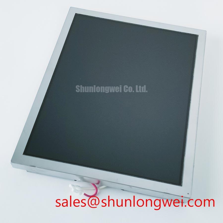
Before mounting the module, place the existing panel and replacement panel side by side and compare the active viewing area, connector exit, mounting points, cable bend path, and bezel opening. The LQ070Y5DG06 is identified as a standard-form-factor TFT-LCD module, not as a complete sealed marine monitor. The enclosure therefore remains responsible for sealing, shock isolation, ventilation, and protection from external contamination.
A perimeter gasket can reduce vibration transfer, but it must not load the active glass area or concentrate force at a corner. Use a cross-pattern tightening sequence when the chassis requires multiple fasteners, applying only the torque established by the equipment manufacturer or mechanical design authority. Excessive clamping can create pressure marks, uneven illumination, or optical mura that may not appear until the display reaches operating temperature.
For bright outdoor consoles, evaluate the assembled screen rather than the bare panel. The viewing angle, cover glass, surface finish, ambient reflections, and enclosure hood all influence readability. Anti-glare and anti-reflective treatments should be confirmed from the actual panel or cover-layer specification; they should not be inferred from the Sharp model number. A clean uniform test image viewed under the intended lighting condition is more useful than a nominal contrast claim considered separately from the enclosure.
⚠️ Field Alert: Remove power before inserting or removing the display cable, and keep the glass supported evenly while fastening the bezel.
Eye-Diagram Voltage Margin and Differential Noise Floor Verification in High-Vibration Bays
Horizontal noise bands, pixel jitter, or intermittent image loss near variable-frequency drive equipment require a complete signal-path check. Inspect the panel connector, controller output, cable shield termination, chassis bonding, and routing relative to motor and inverter conductors. A shielded FFC or LVDS cable may be appropriate when required by the host design, but shielding effectiveness depends on termination continuity and the grounding arrangement at both ends.
Common-mode ferrite components are system-level countermeasures, not automatic accessories for this panel. If they are considered, the designer should assess their effect on the interface waveform, startup behavior, and cable resonance using the installed controller and cable. An oscilloscope eye-diagram or differential probe measurement can distinguish a timing problem from a noise-floor problem when compared with a known-good display path.
Cold-temperature operation deserves a separate optical and timing check. Liquid-crystal response can become slower as temperature falls, producing visible gray-to-gray elongation or image smearing even when the input signal is stable. If the equipment includes a heater or temperature-control circuit, its startup sequence, sensor position, and thermal distribution should be validated by the system engineer. Do not treat a heater strip as an included feature of the LQ070Y5DG06 unless the original assembly documentation specifies it.
For broader enclosure, cabling, and HMI integration guidance, see Industrial Display & HMI Solutions. The same inspection discipline applies when this Sharp module is evaluated for CNC operator panels, industrial control consoles, or marine navigation displays, subject to the host system’s electrical, optical, and environmental requirements.