

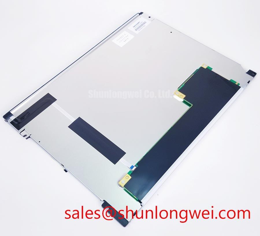


Content last revised on September 30, 2026
Backlight and High-Voltage Checks
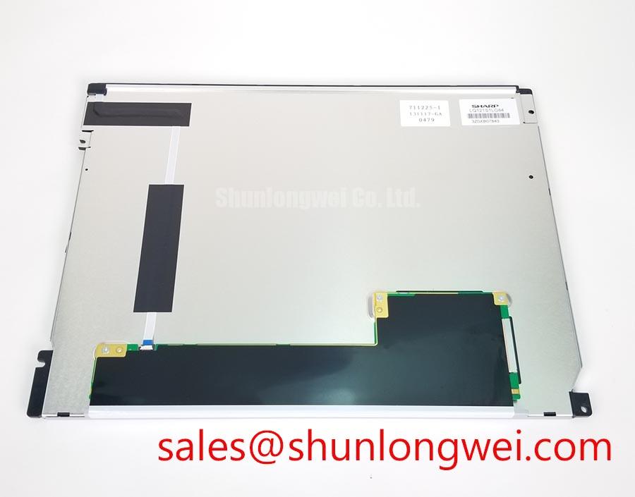
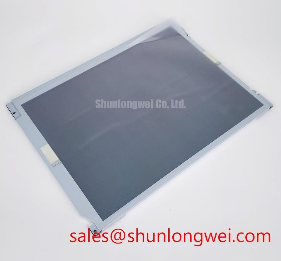
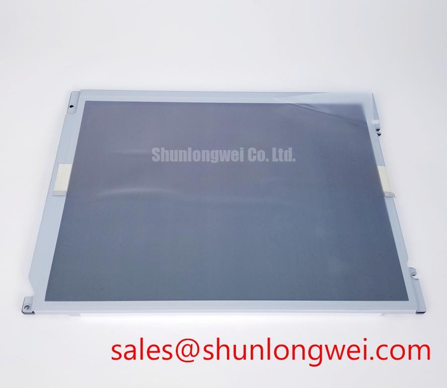
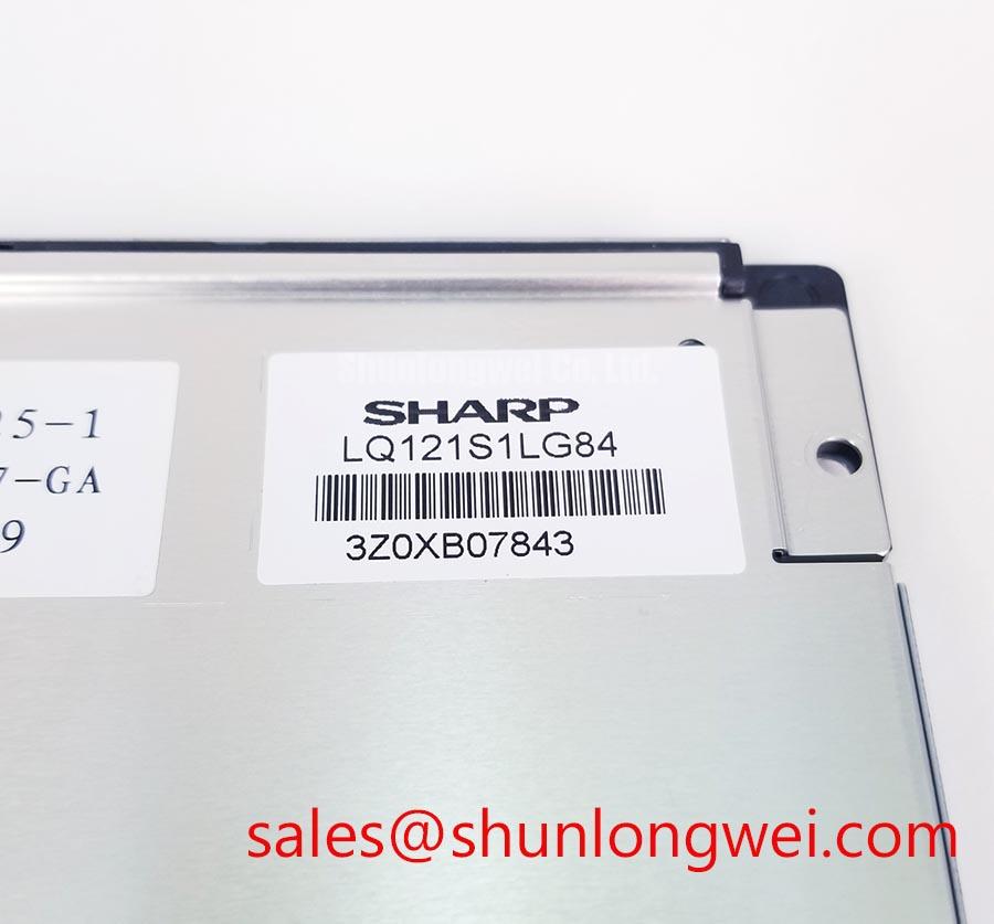
| Model | LQ121S1LG84 |
|---|---|
| Manufacturer | Sharp |
| Product category | Industrial Grade LCD/HMI Panel |
| Display technology | TFT-LCD active matrix color display module |
With the display disconnected from its host, inspect the backlight connector and harness for looseness, discoloration, or damaged insulation, then compare the backlight supply and enable signals with the panel’s approved documentation. The confirmed product information identifies the LQ121S1LG84 as a TFT-LCD active matrix color display module, but does not establish a CCFL or LED backlight type, ignition voltage, dimming method, or lifetime rating. Do not apply a high-voltage test based on assumptions about another panel: identify the backlight circuit first and use the specified service procedure and appropriately rated instruments.
When the image is present but illumination is absent or intermittent, check the host’s backlight control path and connector continuity before attributing the symptom to the panel. If a separate inverter or driver is used in the equipment, assess that circuit independently and observe its safety requirements. A replacement assessment should include connector position, cable routing, mounting points, and the host’s startup sequence, not just the display’s model marking.
Design consideration: Keep backlight power wiring and display signal wiring routed to limit coupling, then verify the result in the assembled equipment under its normal switching conditions.
Color and Image-Uniformity Inspection
Display full-screen red, green, blue, white, and black test images and inspect them from the intended viewing position for persistent pixel defects, uneven illumination, or color shifts. Record the observed pattern and compare it with a known-good unit or the equipment’s acceptance criteria; do not treat a single visual artifact as proof of a specific internal failure. The available confirmed specifications do not state pixel response limits, uniformity tolerances, contrast ratio, surface treatment, or a factory defect class for this model.
For a dark or uneven image, compare the panel’s behavior with the host video output and backlight state. A flashlight inspection can help determine whether image content is present when illumination is missing, but it does not by itself identify the failed circuit or distinguish among panel, driver, and connection faults. Use repeatable test patterns and consistent viewing conditions when documenting a repair finding.
Where the display is evaluated for a railway passenger information terminal or cab signalling display, treat that equipment as a possible integration context, not as proof of qualification for railway service. The system owner should define environmental, optical, and functional acceptance requirements. Sharp’s industrial display solutions provide manufacturer context for display technology, but system-level qualification remains the integrator’s responsibility.
Video Interface and Noise Verification
At the host connector, check that the video interface, pin assignment, signal format, and timing match the panel documentation before powering the assembly. The confirmed information here does not specify whether the LQ121S1LG84 uses LVDS or TTL signaling, nor does it state a JEIDA or VESA mapping, lane count, pixel clock, or cable impedance. Do not infer those details from the screen size or from a visually similar Sharp module.
If the image shows intermittent lines, unstable pixels, or noise that changes with nearby equipment activity, inspect the cable seating, grounding path, shielding continuity, and physical routing. Compare the signal at the source and display ends using suitable probing practices; probe loading and grounding can alter high-speed measurements. Where a differential link is confirmed by the original documentation, assess its pair routing and termination against that interface specification rather than applying a generic value.
Design recommendation: Keep high-speed display paths compact and orderly, and verify signal integrity in the final cable and enclosure arrangement, especially when the display is near switching drives or other noise sources. This is an integration practice, not a guaranteed EMC characteristic of the panel. For broader selection and interface context, see The Ultimate Guide to Industrial TFT LCD Technology.
Temperature, Mounting, and Replacement Fit
Before installing a replacement, compare the module outline, active-area position, mounting features, connector orientation, and cable clearance with the original assembly drawing. The confirmed product information does not provide dimensional drawings, operating or storage temperature limits, response-time behavior, sealing details, or approved fastening torque. Verify those requirements from the applicable panel documentation and the equipment’s mechanical design rather than assuming that a same-size display will fit.
For equipment exposed to temperature variation or vibration, inspect the enclosure support and cable strain relief, then test the assembled display through the system’s defined operating conditions. Temperature-related image changes can involve the panel, host timing, supply behavior, or the wider enclosure environment; record the conditions and reproduce the symptom before deciding on corrective action. No specific thermal-cycle endurance or service-life figure is established here.
For a cross-check during sourcing, compare the documented interfaces and mechanical drawings of the LQ9D340H with the LQ121S1LG84. Similar category or apparent size alone does not establish interchangeability. Confirm the complete electrical and mechanical interface, display timing, optical requirements, and host firmware expectations before treating any alternate module as a candidate.