

Content last revised on October 12, 2026
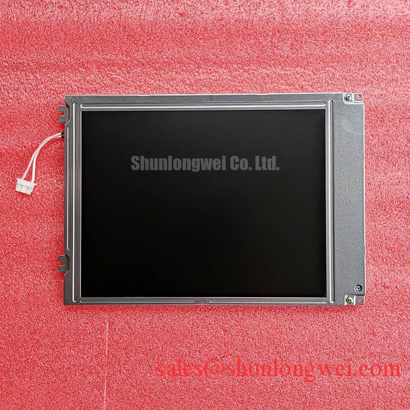
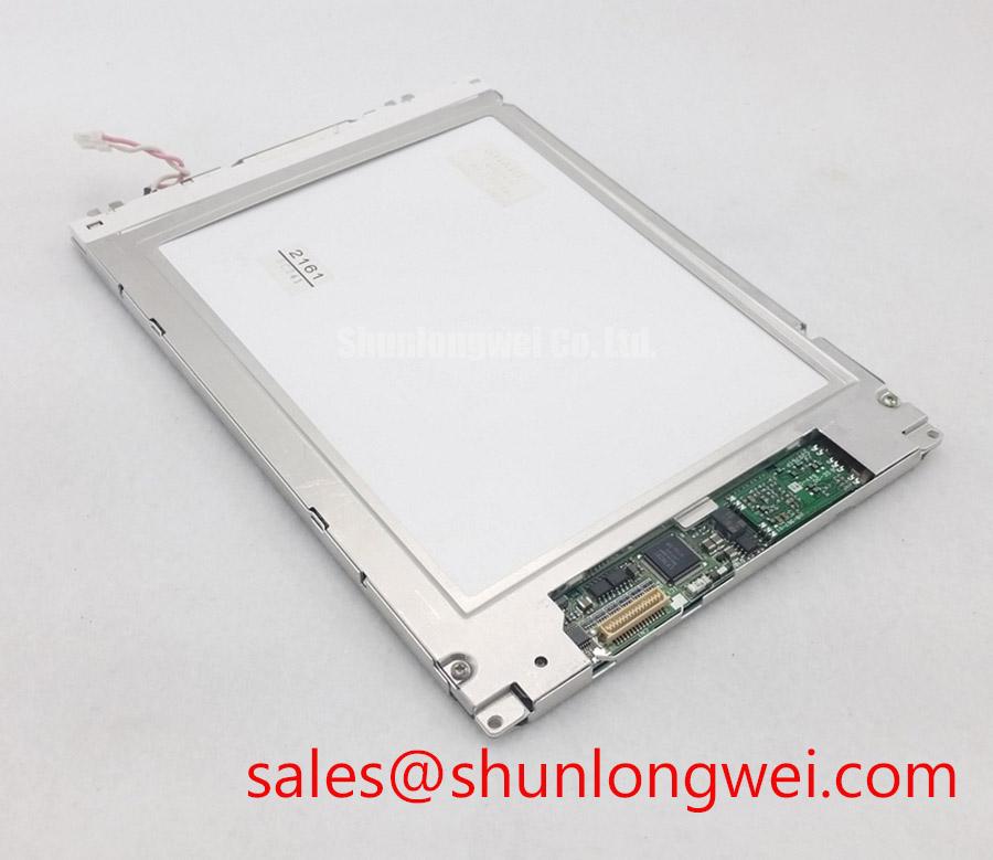
Sharp LQ9D340H TFT LCD Active Matrix Display Module
- Confirm the installed panel identity as Sharp LQ9D340H before removing the existing unit.
- Inspect the enclosure cutout, bezel contact area, gasket seating, and cable routing for mechanical stress.
- Record cold start behavior, visible lines, pixel instability, and backlight response before changing the display assembly.
- Check the display drive circuit, insulation condition, and connector retention with the equipment isolated from power.
The LQ9D340H is a Sharp TFT LCD active matrix color display module. The available product information does not establish a confirmed panel voltage, current rating, native resolution, optical luminance, interface pinout, backlight technology, or physical dimensions. Those values should not be inferred from the model number when planning a field replacement.
| Manufacturer | Sharp |
| Model | LQ9D340H |
| Product category | LCD Display Module |
| Display construction | TFT LCD Active Matrix Color Display Module |
For railway passenger information systems, cab signalling displays, operator consoles, and other industrial HMI equipment, the replacement assessment should begin with mechanical and electrical compatibility rather than visual similarity. The original system documentation remains the controlling reference for supply rails, signal format, connector assignment, backlight drive, touch function, and enclosure dimensions.
Mitigating Gray-to-Gray Response Time Escalation during Cold-Start Machine Power-Up
Low ambient temperature can lengthen liquid crystal transition behavior, so a cold start should be evaluated by observing moving icons, changing numeric fields, and gray level transitions rather than checking only whether the panel illuminates. A slow image change during a sub-zero start may involve panel temperature, source timing, frame rate, backlight control, or the host display controller. Treating the symptom as a confirmed panel defect can lead to an unnecessary replacement.
For equipment with a required evaluation range of, for example, −30°C to +85°C, the system designer should verify that the complete display assembly, sealing arrangement, controller, and enclosure thermal path have compatible environmental ratings. The available product information does not confirm that the LQ9D340H itself carries an operating rating across those temperatures. Thermal cycling should therefore remain within verified component limits and include cold power-up, image transition observation, warm-up behavior, and inspection of the perimeter seal for movement or separation.
A heater strip may be considered as part of the host equipment thermal strategy when cold-start response must be controlled, but it should not be treated as an integrated feature of this panel without supporting documentation. Heater placement, control logic, condensation management, and temperature sensing are system decisions. They should be validated without creating local hot spots or uneven thermal expansion around the display aperture.
Sharp’s industrial display resources provide useful background for evaluating optical and environmental integration requirements; engineers can consult Sharp Devices Europe Industrial Display Solutions when reviewing broader industrial display application considerations.
Suppressing Pixel Jitter and Horizontal White Lines Induced by Adjacent 400V Motor Drives
Pixel jitter and horizontal white bands near a variable frequency drive should first be approached as a signal integrity and grounding investigation. Separate the display cable from motor output conductors, braking wiring, and switching power paths wherever the cabinet layout permits. The LQ9D340H information supplied here does not confirm a particular LVDS pin assignment, cable construction, shield termination, or common mode immunity level, so the original panel drawing and host controller documentation must define the interface.
A shielded FFC or LVDS harness can reduce radiated and conducted interference when its construction and termination match the system interface. A shield connected incorrectly at the connector, interrupted by a long pigtail, or bonded to a noisy chassis point can produce a different result from the intended cable design. Common mode ferrite components are also system level parts; their impedance behavior, placement, and saturation characteristics should be evaluated against the actual switching environment rather than assumed to be included with the panel.
During troubleshooting, compare the display signal at the panel connector with the known good path at the controller side. An oscilloscope can help distinguish timing disruption, common mode movement, supply disturbance, and mechanical connector intermittency. Change one routing or grounding variable at a time so that improvement can be linked to a measurable installation change.
Direct sunlight evaluation should include the complete front assembly, viewing angle, enclosure window, and surface reflections. The supplied LQ9D340H data does not confirm a contrast ratio above 500:1 at 50,000 lux, nor does it confirm a specific anti glare or anti reflective coating. Those optical properties require verification from the applicable panel documentation or incoming inspection data. For display technology context, see The Ultimate Guide to Industrial TFT LCD Technology.
Optical Luminance Degradation Curve and CCFL to LED Modernization Retrofit Pathways
Backlight modernization must be treated as a compatibility project, not as a simple substitution of one lamp technology for another. A legacy assembly may use a high voltage CCFL inverter, while a modernized design may use a constant current LED driver. The available LQ9D340H information does not identify the installed backlight type, lamp voltage, LED current, dimming method, acoustic behavior, or protection thresholds.
Before considering a CCFL to LED retrofit, identify the original backlight connector, inverter enable signal, brightness control method, fault reporting path, and available enclosure space. A replacement driver should be assessed for open circuit response, short circuit response, overvoltage behavior, conducted noise, and thermal dissipation. These features belong to the complete backlight system and should not be claimed as inherent characteristics of the LQ9D340H.
Long term optical assessment is best performed by recording luminance and uniformity at defined operating conditions over the equipment maintenance interval. A claimed 50,000 hour half life or MTBF must come from the applicable manufacturer data and test definition; it cannot be assigned to this model from the available information alone. PWM dimming performance also requires confirmation of the driver and controller combination, particularly where camera systems, optical sensors, or railway information displays can reveal low frequency modulation.
For a replacement comparison, engineers may review LQ150X1DWF1 as a separately listed display option. It should be evaluated neutrally against the original cutout, interface, optical requirements, and controller timing rather than treated as an automatic substitute for the LQ9D340H.
Thermal Expansion Clearance Sizing across Heavy Industrial Metal Enclosure Cutouts
Mechanical installation should allow the display bezel and active area to remain free from uneven enclosure pressure throughout temperature changes. A cutout that is slightly misaligned, a gasket compressed more heavily on one side, or fasteners tightened unevenly can create localized optical nonuniformity, dark areas, or visible mura. These effects depend on the complete panel construction and mounting frame, not on the model number alone.
The supplied information does not establish the LQ9D340H outer bezel envelope, hole pattern, panel thickness, or approved fastener torque. The integrator should obtain those mechanical values from the original installation drawing before machining a replacement aperture. Cross pattern tightening is a sound general installation practice for distributing load, while the final torque must be determined by the panel frame, fastener size, gasket material, and mounting hardware.
Thermal clearance should be checked after the enclosure reaches its normal operating condition. Inspect for bezel lift, gasket displacement, cable pinch points, and changes in dark field uniformity. The same inspection is useful after transport vibration or repeated service access. ⚠️ Maintenance Note: Inspect the cabinet airflow path and display gasket condition during scheduled service so dust ingress and trapped condensation are detected before image quality declines.
When the LQ9D340H is considered for a cab signalling display or passenger information terminal, the final acceptance test should combine image stability, connector retention, enclosure fit, backlight behavior, and the host controller’s power sequencing. The Sharp Display Solutions portal at Sharp Display Solutions Official Portal offers an additional manufacturer resource for industrial display and optics evaluation.