





Content last revised on September 29, 2026
Polarizer Durability and Optical Film Inspection under Direct Industrial Lighting
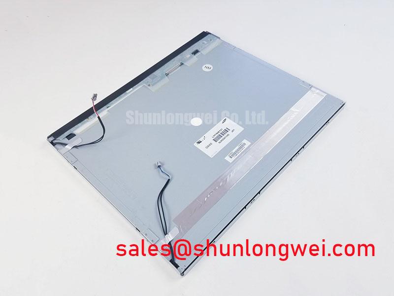
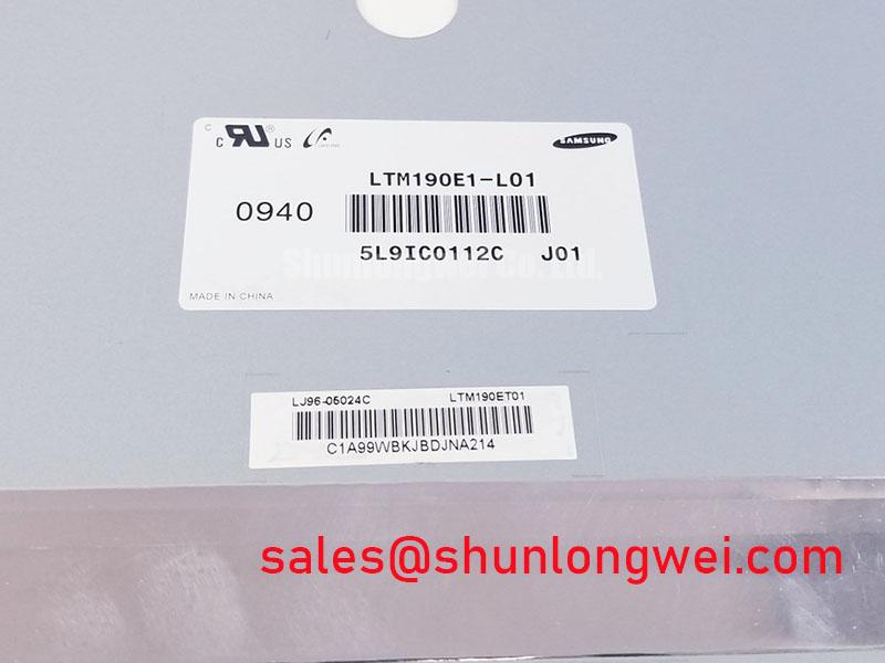
Display a neutral gray test image and inspect LTM190E1-L01 from the operator’s normal viewing positions for uneven shading, reflections and changes in apparent contrast. Repeat the inspection with the cabinet lighting on and off. A screen that looks acceptable on a bench can become difficult to read beneath overhead task lighting, particularly when the operator views it from above or to one side. Record the viewing position and lighting condition with each observation so that a replacement can be judged against the same conditions.
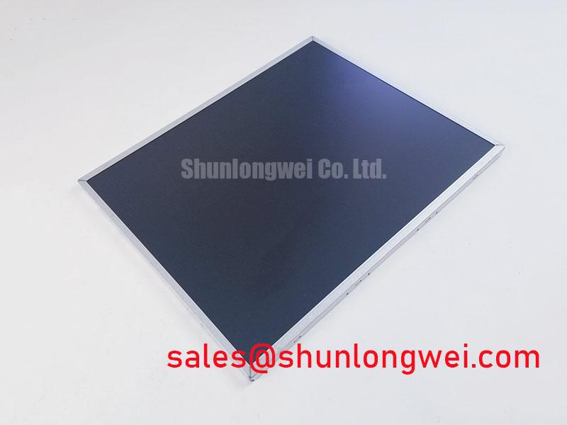
Look across the powered-off front surface with a low-angle light. Scratches, cloudy patches and edge lifting are easier to distinguish from displayed-image defects when no image is present. Then show full-field gray, white and dark images, comparing any visible patch with the same area of the unpowered surface. This separates a surface observation from a symptom that appears only while the display is operating; it does not, by itself, establish which layer or circuit is responsible.
TN grayscale inversion and the wider viewing cones associated with IPS or MVA are useful concepts when evaluating an operator station, but the supplied specifications do not establish which optical mode LTM190E1-L01 uses. Treat an advertised symmetric viewing angle or anti-glare finish as an unverified compatibility claim until the original panel documentation and a physical sample support it. As a Design Consideration, compare legibility from the actual seated and standing sightlines rather than relying on a straight-on photograph.
If the image flickers or loses columns as the cabinet warms, capture the source-side display signals and the panel-side signals with suitable instruments, following the equipment’s service procedure. Compare clock stability and data timing with a known-good assembly under the same operating conditions. TTL and LVDS require different measurement approaches; neither interface is confirmed by the supplied panel parameters. The integrator should establish the connector assignment, timing limits and operating-temperature window from the original panel and host documentation before interpreting a waveform. The VESA Video Electronics Standards Association provides industry display standards and testing context, but an applicable standard must be identified before its limits are applied to this module.
Backlight Heat Distribution and Light Guide Preservation
Inspect the narrow edges of the display for a localized bright or dark band after the assembly reaches its normal operating condition. Photograph the same test image at startup and after warm-up with fixed camera exposure. A changing edge pattern may justify checking backlight drive, thermal contact and bezel pressure separately; it does not prove that the light guide has yellowed. Keep the panel in its installed orientation during this comparison, since an open-bench test may change airflow and mechanical loading.
The supplied factory parameters do not identify the backlight as LED, state its brightness or establish the light-guide material. Consequently, an edge-lit LED rail, a PMMA plate and an L70/B50 life rating cannot be assigned to LTM190E1-L01 as specifications. Where the original display assembly does use an edge-mounted light source, a Design Consideration is to check whether its intended heat path remains in contact with the enclosure and whether wiring or a displaced gasket obstructs airflow. Measure accessible temperatures using the equipment maker’s service method, and compare results with the limits for the documented assembly rather than an assumed panel limit.
Inspect the cabinet’s dust seals and cooling path together. A clogged vent can change internal temperature while a flattened or misaligned gasket can leave an opening for dust and humid air. Neither condition is corrected by increasing backlight output. Where an enclosure uses optical bonding or a front protective window, examine the complete stack for haze, trapped contamination or separation without assuming that this bare display module was factory bonded. Moisture control belongs to the finished enclosure: check its sealing condition and temperature transitions against the station’s approved maintenance procedure.
For a high-ambient-light installation, compare the displayed image at the intended viewing position under representative illumination. Do not treat a contrast figure measured in one lighting setup as a guarantee of readability in direct sunlight. The supplied parameters give no sunlight contrast, coating or luminance rating for this model. Engineers assessing another display assembly, such as LQ190E1LW42, should compare each unit’s documented electrical interface, backlight arrangement, mechanical drawing and optical test conditions; a similar product name does not establish interchangeability.
Chassis Fastening, Bezel Pressure and Mura Inspection
Loosen the surrounding chassis hardware according to the equipment service procedure, then check whether a dark-field patch changes when bezel pressure is released. If it does, inspect the gasket seating, bracket flatness and contact points before attributing the mark to a failed display. Observe the screen again after reassembly using the same image and viewing angle. This pressure-sensitive comparison is especially useful when a panel looks uniform outside the cabinet but develops a mark once clamped into the operator station.
Measure the mounting features and outer envelope against the original mechanical drawing before ordering replacement hardware or altering brackets. The supplied specifications do not establish an M3 fixing pattern, bezel tolerances or an approved torque for LTM190E1-L01. A Design Consideration is to tighten the enclosure hardware progressively and evenly, using the fastener and torque instructions for the actual chassis. The aim is consistent gasket contact without concentrated loading on the display edge; the equipment design determines the required compression.
Maintenance Note: Check the cooling path and perimeter gasket during scheduled service, and disconnect power before disturbing display cables.
Keep a record of where the visible patch lies relative to clips, screws and gasket joints. A stain-like mark that persists with the panel mechanically unloaded calls for a different investigation from a mark that shifts as a bracket is adjusted. Avoid pressing on the active area to “test” the defect: that introduces a new load rather than isolating the installed one. If the enclosure includes a protective cover, inspect its clearance and seals separately from the display so that reflections or moisture on the cover are not mistaken for panel mura.
For brightness complaints, establish the backlight-control scheme from the original controller and panel documentation. The supplied parameters specify neither PWM operation nor a dimming-frequency range. If the documented assembly uses PWM, compare control input and light output across its normal adjustment range while listening for enclosure vibration and watching for visible flicker. Determine acceptable settings at system level; changing an undocumented dimming setting can obscure the original fault.
During a replacement assessment, compare the connector location, active area, mounting drawing, optical performance and control requirements rather than matching a diagonal size alone. HLM8620-6 can be included in that comparison, but compatibility is not established by its listing here. The existing harness and chassis drawings remain the reference for fit and integration.
Pixel Jitter and Horizontal Lines near Motor-Drive Cabling
Capture the horizontal-line symptom while the adjacent motor drive is stopped, starting and running, without changing the display settings between observations. Note whether the disturbance follows drive activity, cabinet-door position or movement of the display cable. Correlation narrows the inspection area but does not identify a single cause: source video, connector contact, supply disturbance and cable coupling can produce symptoms that look similar on screen.
Trace the display cable from controller to panel and inspect its routing, strain relief and shield termination against the equipment wiring drawing. Keep it clear of motor-drive power wiring where the cabinet design permits, and check that a shielded connector makes the intended chassis contact. A continuous, well-terminated shield is a Design Consideration for controlling coupled noise, not proof that this module uses LVDS or that a particular grounding arrangement suits every controller. Do not add a ferrite or alter a termination simply because white lines appear; compare measured signals at both ends and test any proposed change in the complete equipment.
If a panel-side waveform differs from the controller output, inspect cable bends and connector seating before changing electronics. If both ends show the same disturbance, examine the upstream video source and its supply under the conditions that reproduce the fault. Use the documented interface and a suitable probe so the measurement itself does not load the link. The system integrator should verify the required supply voltage and signal pinout from the original panel documentation rather than infer either from the module name.
A hazardous petrochemical Zone 2 operator station is a possible enclosure-level compatibility assessment, not an application approval for LTM190E1-L01. Check the station’s applicable enclosure approval, sealing, thermal arrangement and cable-entry rules independently. For wider context on display selection and operating-condition checks, use The Ultimate Guide to Industrial TFT LCD Technology alongside the equipment’s service records. Complete the fault check by repeating the same display test image and motor-drive operating sequence after the cable and enclosure are restored to their documented configuration.