Content last revised on October 19, 2026
Preventing Localized Light Guide Plate Compression Warp on Dark Screen Fields
Dark-field mura inspection should begin with the panel mounted in its intended support frame rather than held by one corner. Uneven bezel pressure can create localized optical non-uniformity that changes when fasteners are loosened, so compare a uniform black, grey, and white test image before and after final fastening. This distinguishes a mechanical loading effect from a source-image, timing, or backlight-driver problem without assigning a single cause to the symptom.
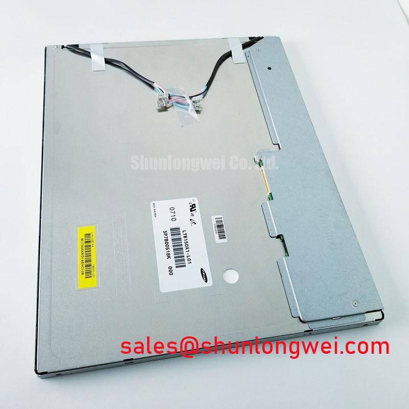
For a fixture using cross-pattern M3 fasteners, 0.35–0.45 N·m is a general Design Consideration for controlled mounting torque, not an official M150XN04 V1 factory specification. Tighten progressively in a diagonal sequence while checking that the outer bezel remains planar and that no fastener head contacts the active viewing area. The chassis opening should be established from the original equipment drawing; do not compress the panel to compensate for an undersized envelope or unsupported edge.
High-EMI cabinets also require a clean differential routing strategy. A commonly used Design Consideration for LVDS-style links is approximately 100 Ω ± 10% differential impedance, with pair lengths controlled so that lane skew remains within the transmitter and receiver timing budget. These values describe a host-board routing target, not a confirmed internal specification of this display. Keep the cable away from switching nodes, avoid sharp bend transitions at the connector, and validate the eye opening at the panel input when the enclosure is fully assembled.
Use the Innolux industrial display portfolio and the AUO industrial display and embedded systems information as manufacturer-level references when comparing mechanical and interface documentation. For cross-model evaluation, the TX26D14VM2EAA should be treated as a separate engineering candidate, not an automatic substitute, until dimensions, connector assignment, timing, and optical characteristics are matched.
20-Pin/30-Pin Differential LVDS Timing, Pixel Clock and Skew Compensation
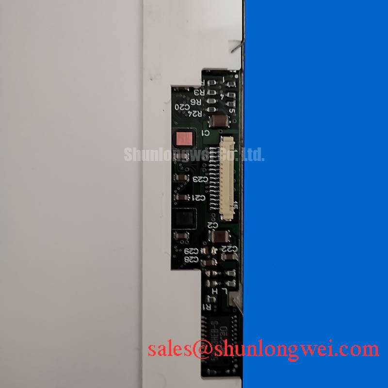
Before investigating split-screen artifacts, identify the actual connector population and map every signal from the controller board to the panel documentation. A 20-pin or 30-pin appearance alone does not establish pin assignment, voltage, channel arrangement, or JEIDA/VESA mapping. The integrator should verify whether the host output format matches the panel receiver and should not reuse a cable solely because its connector shell appears compatible.
For a host design that specifies a logic rail of 3.3 V or 5.0 V, measure the rail directly at the panel-side connector during startup and shutdown. A power-on rise interval of 0.5 ms < t1 < 10 ms can be used as a system timing check only where the original controller documentation requires it; it is not a confirmed M150XN04 V1 rating. Capture the logic rail, enable signal, pixel clock, and differential activity on the same time base to identify sequencing overlap or an early data stream.
For differential routing, the 100-ohm target should be maintained through connector transitions, vias, and cable launches where the board stack-up supports controlled impedance. The system engineer should compare positive and negative transition timing at the panel connector, then adjust trace length or source timing only after confirming the transmitter data sheet limits. Excessive skew can appear as color displacement, repeated image sections, or intermittent vertical bands, while an incorrect JEIDA/VESA mapping can produce stable but incorrect grayscale and color order.
Cold-environment testing requires a separate optical and timing check. Liquid-crystal response can lengthen as temperature falls, producing visible grey-to-grey trailing even when the pixel clock remains stable. If the equipment includes a heater strip, its control loop should be evaluated for temperature overshoot, local gradients, and startup behavior rather than assumed to be part of this panel. A camera-based motion test, a grey ramp, and a known-good controller provide more useful evidence than a single static image.
💡 Bench Tip: Disconnect power before inserting or removing the display cable, then verify that the cable is fully aligned and evenly latched on both sides before applying power.
Aluminum Heat Spreader Sizing and Thermal Interface Placement along Narrow Display Edges
Thermal work around a narrow display edge should start with a temperature map taken at the backlight driver area, connector region, bezel, and exposed chassis surfaces. An aluminum spreader rail may reduce a local hot spot when it has a defined thermal path to the enclosure, but it can also transfer heat into a sensitive edge if the contact area and insulation are poorly controlled. The M150XN04 V1 baseline does not confirm an aluminum rail, PMMA light-guide construction, LED lifetime rating, or L70/B50 value as a factory specification.
Use a thin, even thermal interface only where the mechanical drawing permits it, keeping pressure away from the active glass and avoiding contact with exposed conductors. The enclosure designer should determine whether the rail is structural, thermal, or both, then validate the result under the actual backlight duty cycle. A claimed 50,000-hour MTBF or LED life figure must not be assigned to this model without a manufacturer-issued rating and its defined temperature, current, brightness, and failure criteria.
Display reliability testing should include brightness uniformity, edge temperature, connector temperature, and color drift after warm-up. When a constant-current LED driver is used in the host system, verify open-load and short-load protection at the driver output and confirm that its fault signal is understood by the controller. The protection behavior belongs to the backlight electronics unless the panel documentation explicitly assigns it to the display module.
TTL or LVDS transmitter jitter, clock duty cycle, and data hold time should be checked across the specified industrial temperature window of the complete system. A thermal spreader cannot correct a marginal clock path, and a clean eye diagram does not prove optical uniformity. Keep electrical timing validation and thermal qualification as separate test records.
Dynamic Contrast Ratio Stabilization and Liquid Crystal Birefringence Temperature Tracking
Evaluate contrast and viewing behavior using controlled grey ramps at the actual installation angle, ambient illumination, and backlight setting. TN, IPS, and MVA labels must come from the applicable panel documentation; they should not be inferred from a photograph or connector arrangement. If the application requires a symmetric viewing cone of 85°/85°/85°/85°, treat that as a comparison criterion only when it is explicitly specified for the selected panel.
Dark-screen evaluation under strong room lighting should separate surface reflection from liquid-crystal contrast. An anti-glare or anti-reflective surface can improve readability, but etching, coating, and viewing angle affect sparkle, haze, and perceived black level differently. Use the same luminance meter position and the same test pattern when comparing the installed unit with the original display. The M150XN04 V1 baseline confirms an industrial TFT-LCD color module, but it does not confirm a particular AG or AR treatment.
At sub-zero temperatures, birefringence changes and slower liquid-crystal transitions can alter grey-scale tracking, shadow detail, and motion response. If a heater is fitted by the equipment manufacturer, place temperature sensors near the display edge and controller area to check whether the panel warms uniformly. PWM backlight behavior should also be reviewed with a photodiode or oscilloscope: a proposed 200 Hz–1 kHz control range is a system tuning consideration, not a confirmed flicker-free specification for this model.
For high-voltage substation protection and SCADA dispatch consoles, assess readability with alarm colors, thin line graphics, and low-level grey information screens rather than relying only on a white field. The practical reference for enclosure ventilation, optical inspection, and harsh-environment integration is available in Industrial Display & HMI Solutions. Any final replacement decision should be based on connector compatibility, timing behavior, mechanical fit, optical inspection, and the complete host-system test record.