

Content last revised on October 28, 2026
MBN600E45A Thermal-Electrical Optimization: Preventing Internal Leadframe Cracking during Practical Tuning
- Isolate the equipment, verify DC-link discharge, and record cold-state readings across the identified power terminals before disconnecting the module.
- Check busbar alignment, terminal screw engagement, and washer seating without using fasteners to pull misaligned conductors into position.
- Inspect the heatsink contact surface, cooling passages, and existing thermal interface for contamination or uneven contact.
- Match the gate-drive connections and power-terminal assignments to the equipment schematic before preparing replacement work.
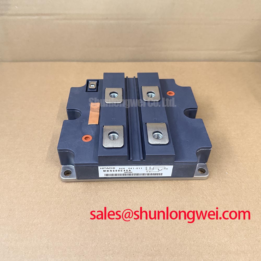
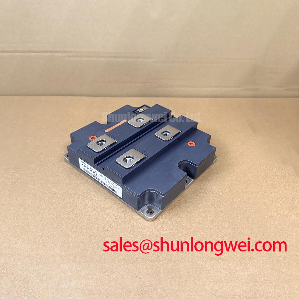
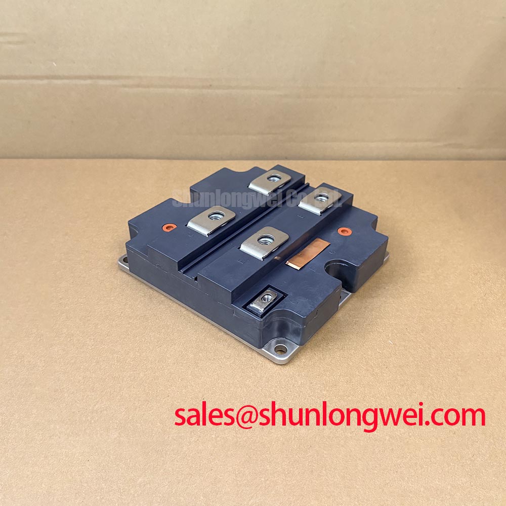
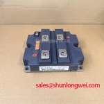
The MBN600E45A is a Hitachi IGBT module identified with a high-power isolated module package. For maintenance planning, separate the component identity from the assembly conditions that determine its operation: terminal loading, cooling contact, gate-drive behavior, and protective shutdown.
| Product identification | Specification status |
|---|---|
| Model | MBN600E45A |
| Manufacturer | Hitachi |
| Product category | IGBT module |
| Package description | High-power isolated module |
| Voltage and current ratings | Consult Datasheet for numerical ratings and associated temperature conditions. |
| Terminal map, dimensions, and tightening specifications | Consult Datasheet and the applicable mechanical drawing. |
Check terminal screw engagement against the terminal drawing before tightening the main conductors. A screw that bottoms in a threaded connection can produce an apparently firm joint without establishing the intended clamping force. Incorrect washer arrangements can also change engagement and contact pressure. Record the approved hardware stack and use a calibrated tool with the specified tightening procedure.
Design Consideration: support busbars independently so their weight, vibration, and thermal movement do not lever against the module terminals. Check alignment with the hardware relaxed; the mating faces should meet without forced displacement. This limits externally applied mechanical stress without assuming any particular internal leadframe or conductor construction inside the MBN600E45A.
After controlled operation, compare terminal temperature patterns under comparable load and cooling conditions. A localized increase warrants examination of contact resistance, surface condition, conductor loading, and clamping integrity rather than an immediate diagnosis of internal damage. Preserve accessible inspection points and the equipment’s required electrical clearances when repositioning supports.
For replacement assessment, the FF400R33KF2 is a separate comparison candidate, not an established interchangeable replacement. Compare blocking capability, current conditions, switching behavior, circuit configuration, terminal locations, and mounting geometry before making a substitution decision.
Field Diagnostics & Commissioning: Optimizing Heatsink Contact Pressure in MBN600E45A Topologies
Clean the mating surfaces and inspect the previous thermal interface imprint before applying fresh material. Uneven transfer can identify areas requiring further flatness or assembly checks, although the imprint alone does not establish the cause. Remove debris without scratching the contact surface and keep thermal compound away from electrical connections.
Design Consideration: control thermal interface material application through the approved material instructions and module mounting procedure. Excess compound can increase thermal resistance, while incomplete coverage can leave poorly coupled regions. Set the application method and finished bond-line requirement from the actual interface specification rather than adopting a generic thickness. Do not use extra compound to conceal an unacceptable mounting surface.
Bring mounting screws into contact progressively using the approved sequence. Check that cable restraints and busbar supports do not change module seating as the electrical connections are secured. Verify terminal assignments against the circuit drawing, then inspect clearance around conductors, washers, and nearby grounded metal.
When evaluating the MBN600E45A for a heavy-duty variable-frequency AC motor drive, engineers should check the complete power-stage and cooling requirements. The control approach described in Direct Torque Control (DTC) for High Dynamic Industrial Induction Motor Drives provides operating context, not evidence of module compatibility. Likewise, an IXTN79N20 considered for an auxiliary switching stage requires its own electrical assessment; it is not a substitute for the main module or automatically suitable for the rectifier stage.
Benchtop Waveform Tuning: Mitigating Commutation and Turn-Off Voltage Stress on MBN600E45A
Capture switching voltage and current with appropriately rated probes and a measurement arrangement that minimizes pickup. Correlate overshoot with the actual commutation event before changing components: probe-loop artifacts can resemble power-stage ringing. Establish the gate waveform at the device connections rather than relying only on the driver output.
Design Consideration: where the verified circuit includes an antiparallel freewheeling diode, evaluate peak reverse-recovery current and recovery abruptness alongside switch turn-on behavior. These interactions can increase transient stress and emissions. Adjusting turn-on gate resistance or evaluating an RC snubber involves a trade-off between damping, switching loss, and component heating; values should follow measured system behavior and component limits.
Keep the gate-current path compact and separate it from high-current commutation routing. If the documented terminal arrangement provides a dedicated auxiliary emitter connection, use it according to that arrangement rather than assuming every terminal offers an equivalent driver return. Check isolator common-mode transient immunity against measured switching conditions when investigating unexplained gate disturbances.
For desaturation protection, examine sensing behavior, blanking, propagation delay, and controlled turn-off as a coordinated sequence. Validate protection against the applicable short-circuit operating limits without inventing a universal threshold or delay. The distributor’s Peak Efficiency in Solar and Energy Storage guide offers broader topology context; it does not establish MBN600E45A switching ratings or protection settings.
Preventing Spurious Faults: Mounting and Thermal Guidelines for MBN600E45A
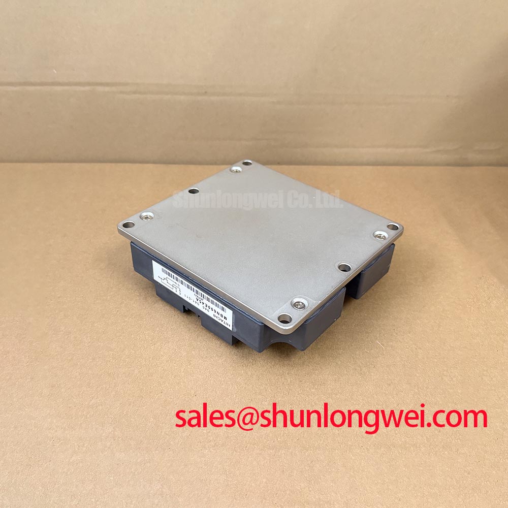
Check mounting-surface flatness and module seating before treating repeated thermal trips as a semiconductor fault. Measure baseplate profile using the manufacturer’s inspection method; visible curvature is not, by itself, proof of damage. Do not assume a copper baseplate or a particular ceramic substrate construction without the relevant drawing.
Design Consideration: where the mounting instructions specify diagonal tightening, follow that sequence progressively with a calibrated tool. Uneven clamping can distort the assembly and disturb thermal contact. Avoid additional tightening as a response to high temperature until airflow, interface condition, loading, and sensor behavior have been checked.
Maintenance Note: Monitor terminal temperature trends and cooling airflow during scheduled inspections before deciding whether a connection or thermal interface needs intervention.
Set inspection intervals from duty, contamination, and observed condition rather than an invented module service life. Check for thermal material migration, obstructed fins, loose supports, and condensation after temperature transitions. Allow moisture-affected equipment to recover under the site’s approved procedure before energization. Record load and cooling conditions with temperature measurements so later comparisons distinguish an assembly change from a changed operating point.