Scan Part Number

Tap the focus box or CAPTURE to scan the part number.

Pinch screen or tap 1.4x button to zoom.

Recognizing Part Number...

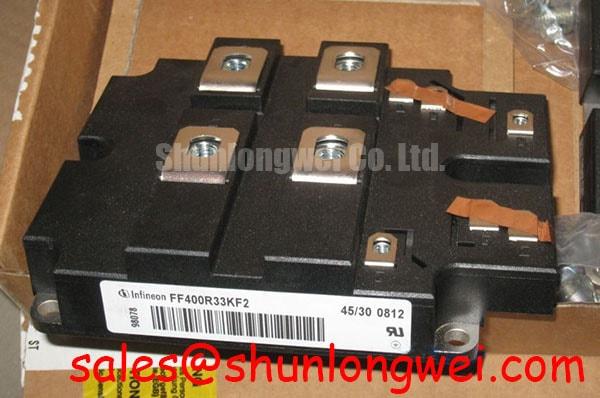
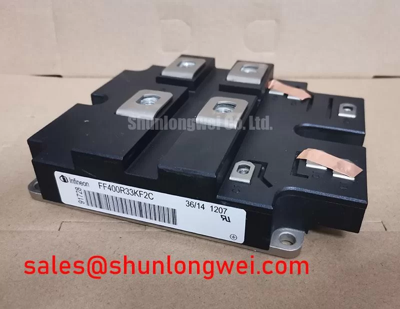
FF400R33KF2 Infineon 3300V 400A Dual IGBT Module

FF400R33KF2 IGBT Module In-stock / Infineon: 3300V 400A. IHM-B package for traction & wind power. 90-day warranty. Global fast shipping. Get quote.

· Categories: IGBT
· Manufacturer: Infineon
· Price: US$ 182 In-Stock Offer
· Date Code: Please Verify on Quote
. Available Qty: 30
90-Day Warranty
Global Shipping
100% Tested
Whatsapp: 0086 189 2465 1869

Content last revised on June 23, 2026

FF400R33KF2 Infineon 3300V 400A Dual IGBT Module

The Infineon FF400R33KF2, a cornerstone of the IHM-B module family, is a high-performance dual IGBT module designed to address the rigorous demands of medium-voltage power conversion. By integrating 3300V TRENCHSTOP™ IGBT3 technology with an EmCon 3 diode, this module provides engineers with a robust switching platform that prioritizes thermal cycling reliability and low conduction losses. For systems operating on 1500V DC buses, such as those found in renewable energy and traction applications, the FF400R33KF2 offers the necessary voltage overhead to ensure long-term operational safety and efficiency.

3300V | 400A | AlSiC Baseplate

  • Enhanced Reliability: AlSiC baseplate offers superior thermal expansion matching to reduce mechanical stress.
  • High Efficiency: Low Vce(sat) minimizes conduction losses in continuous high-load industrial environments.

Engineers often inquire about the dielectric strength for high-altitude or grid-tied applications; the FF400R33KF2 addresses this with an insulation voltage (Visol) of 6.0 kV AC (for 1 minute), ensuring compliance with international safety standards for high-power electronics. For HVDC or traction inverter designs prioritizing thermal margin, this 3300V module is the optimal choice.

Key Parameter Overview

Decoding the Specs for Enhanced Thermal Reliability

The following technical specifications are derived from official engineering documentation and represent the nominal operating characteristics of the FF400R33KF2. This data is critical for accurate thermal management and heatsink dimensioning during the system design phase.

Main Parameter Specified Value Engineering Significance
Collector-Emitter Voltage (Vces) 3300V Ensures safety margin for 1500V DC link systems.
Continuous DC Collector Current (Ic) 400A (at Tc = 80°C) High current density in the standard IHM-B package.
Collector-Emitter Saturation Voltage 3.00V (at 400A, 25°C) Directly impacts efficiency and cooling requirements.
Repetitive Peak Collector Current (Icp) 800A Defines the Short-Circuit Safe Operating Area.
Insulation Test Voltage (Visol) 6.0 kV Required for high-voltage isolation safety.
Baseplate Material AlSiC Matched CTE for maximum power cycling capability.

Download the FF400R33KF2 datasheet for detailed specifications and performance curves.

Application Scenarios & Value

Achieving System-Level Benefits in High-Voltage Power Conversion

The FF400R33KF2 is frequently utilized in traction inverters and wind power systems, where the combination of high voltage and variable load cycles presents a significant engineering challenge. A critical advantage of this module is its AlSiC baseplate. Think of the baseplate as the foundation of a skyscraper; if it expands at a different rate than the building itself during a heatwave, the structure will crack. In the FF400R33KF2, the AlSiC material has a Coefficient of Thermal Expansion (CTE) that closely matches the ceramic substrate, effectively eliminating the solder fatigue that typically leads to premature failure in standard copper baseplate modules.

In the context of industrial automation and high-power drives, the 3300V rating provides a buffer against voltage transients caused by inductive loads. This is particularly relevant for Variable Frequency Drive (VFD) systems operating in harsh electrical environments where grid instability is common. For systems requiring even higher current handling within the same voltage class, engineers may also consider the FZ1200R33KF2C, which offers a 1200V current rating.

For more detailed insights on how these components integrate into complex systems, engineers can refer to the engineer's ultimate guide to IGBT modules. Proper gate drive design is also paramount, as the FF400R33KF2 requires a precise gate voltage to minimize switching losses and prevent IGBT failure due to desaturation.

Industry Insights & Strategic Advantage

Meeting the Demands of Grid Modernization and Carbon Neutrality

As the global energy landscape shifts toward carbon neutrality, the role of high-voltage power semiconductors has moved from the periphery to the core of strategic infrastructure. The Infineon FF400R33KF2 serves as a critical enabler for high-efficiency power systems, particularly in the scaling of offshore wind energy and HVDC transmission. Modern regulatory frameworks, such as the IEC 61800-3 standard for adjustable speed electrical power drive systems, increasingly mandate higher efficiency and electromagnetic compatibility, areas where the IGBT3 technology excels.

The transition to 3.3kV platforms allows for higher system voltages, which in turn reduces the current required to transmit the same amount of power. This reduces the size and weight of copper cabling and transformers, lowering the total cost of ownership (TCO) for large-scale utility projects. Furthermore, the integration of TRENCHSTOP™ technology reduces the total power dissipation, allowing for higher power density in inverter cabinets. This is a vital factor in space-constrained applications like traction converters in high-speed rail, where every kilogram and cubic centimeter saved translates into increased energy efficiency for the vehicle.

FAQ

How does the AlSiC baseplate of the FF400R33KF2 impact long-term reliability?
The AlSiC (Aluminum Silicon Carbide) baseplate provides a Coefficient of Thermal Expansion (CTE) that is closely matched to the internal ceramic insulation. This minimizes the thermomechanical stress during power cycling, significantly reducing the risk of solder delamination and extending the life of the module compared to copper-based alternatives.

What is the primary benefit of the EmCon 3 diode used in this module?
The EmCon 3 (Emitter Controlled) diode is optimized for soft recovery characteristics and low reverse recovery charge. This results in lower switching losses and reduced electromagnetic interference (EMI) during high-frequency operation, making it easier to meet stringent EMC standards.

What is the maximum junction temperature for the FF400R33KF2 under switching conditions?
The module is specified for an operation temperature (Tj op) up to 125°C. Staying within this thermal limit is essential for maintaining the Safe Operating Area (SOA) and ensuring the module can handle transient overloads without catastrophic failure. For thermal design best practices, see Infineon IGBT Module documentation.

For technical procurement and engineering support regarding the FF400R33KF2 or related high-power components, contact our technical sales team. We specialize in providing detailed data and logistics support for OEM manufacturers globally.

More from Infineon

Infineon
Infineon
Infineon
Infineon
Infineon