
Content last revised on October 28, 2026
Transient Dynamics & Electrical Design: Dynamic Firing Delay Angle Adjustment on MCC501-16IO1B
- Isolate the supply, verify stored energy has discharged, and identify anode, cathode, and gate connections against the equipment schematic.
- Compare cold terminal measurements with the disconnected circuit and a serviceable reference; do not treat a single resistance reading as a complete thyristor test.
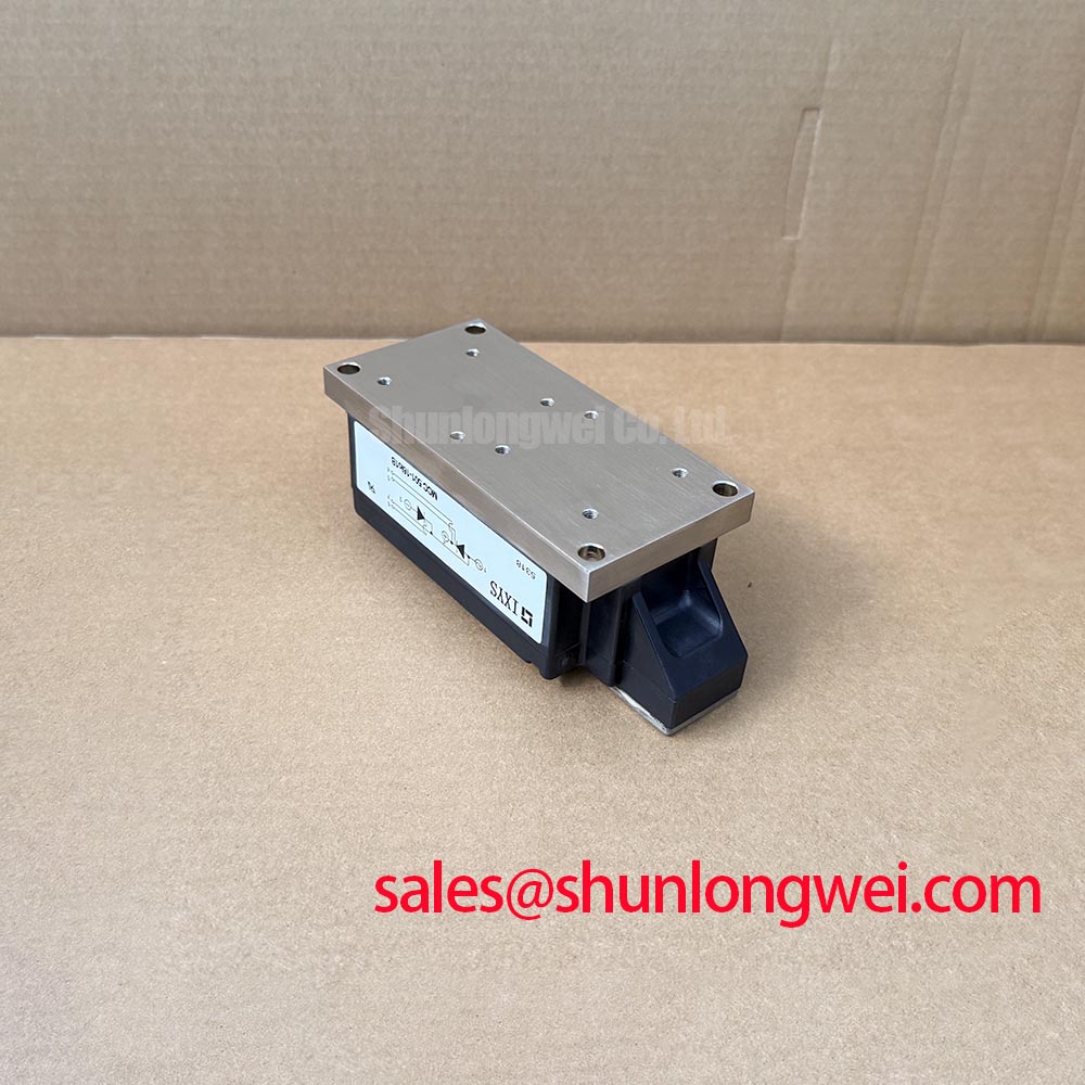
- Inspect the heatsink contact surface, terminal seating, and gate wiring before reconnecting the power circuit.
- Check firing synchronization and current feedback before attempting a powered rectifier test.
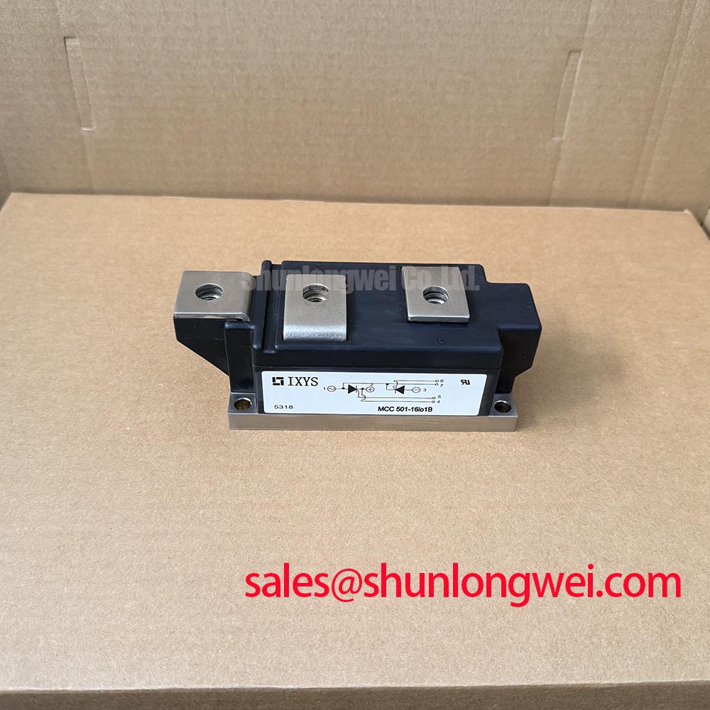
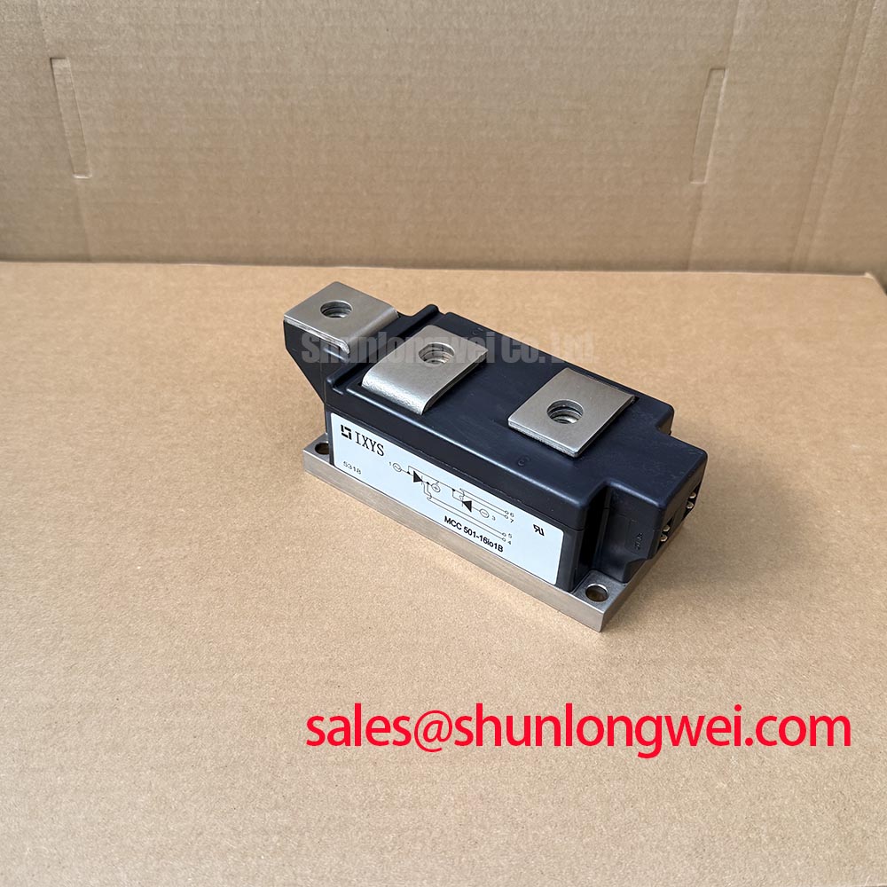
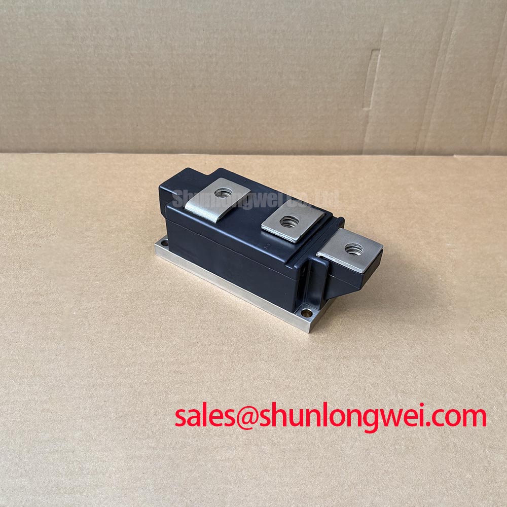
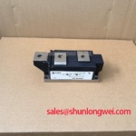
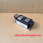
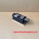
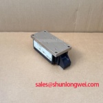
The MCC501-16IO1B is an IXYS dual thyristor module with specified ratings of 1600 V and 501 A. Its integration centers on synchronized firing, controlled current rise, natural commutation, and thermal management—not the PWM gate control used for IGBT or MOSFET modules.
| Product characteristic | Specified value |
|---|---|
| Manufacturer | IXYS |
| Model | MCC501-16IO1B |
| Product category | Dual thyristor module |
| Voltage rating | 1600 V |
| Current rating | 501 A, subject to datasheet conditions |
| Package | Module |
| Rating conditions and assembly details | Consult Datasheet for current-rating conditions, terminal diagram, gate limits, surge data, and mounting torque. |
Compare each gate pulse with its corresponding supply phase before changing the firing delay. As a Design Consideration, increasing delay generally reduces average rectified output in a fully controlled bridge with continuous current, while increasing displacement-related reactive demand. Discontinuous conduction, source impedance, and commutation overlap change that relationship; measured output should therefore be interpreted alongside load current and phase voltage.
A firing-angle sweep from zero to 150 degrees is an evaluation range, not a guaranteed operating envelope for this module. Beyond the rectifying region, sustained inverter operation requires appropriate DC-side conditions and sufficient commutation margin. For repair assessment, record firing symmetry, missed conduction intervals, and output ripple rather than assuming that controller angle commands establish actual device conduction.
Engineering Recommendation: Verify gate-trigger current and voltage against the manufacturer's trigger characteristics, together with permitted gate pulse power. Pulse-train triggering can support reliable latching under changing load conditions, but pulse amplitude, duration, and repetition must remain within gate limits. Route each trigger return with its corresponding gate connection to reduce interference from the power circuit.
For replacement assessment, compare MCC95-16IO1B by circuit arrangement, current capability, cooling requirements, terminal geometry, and trigger characteristics; the related designation does not establish direct interchangeability. A high-current green hydrogen electrolyzer DC power rectifier is one potential compatibility assessment, subject to its bridge configuration and load-control requirements.
MCC501-16IO1B Operational Boundaries: Evaluating Turn-On Current Rise Limiting: Preventing Limits
Separate excessive anode current rise during commanded firing from unintended triggering during a rapid voltage transition. As a Design Consideration, turn-on current-rise control limits stress while conduction spreads through the thyristor, whereas an RC snubber addresses voltage slew and circuit ringing. Neither function substitutes for correctly coordinated fault protection.
Snubber evaluation should account for applied voltage, commutation-loop inductance, repetitive capacitor discharge, and resistor pulse heating. A series reactor requires assessment of its initial inductance, saturation behavior, load-current range, and effect on commutation. Component values belong to the complete rectifier design and should follow measured waveforms under representative supply and load conditions.
For semiconductor fuse coordination, compare total clearing I²t at the relevant prospective fault current and voltage with the module's applicable withstand data. Include initial junction temperature, surge duration, and the distinction between pre-arcing and total clearing energy. Matching headline current ratings alone does not establish protection coordination or containment performance.
Practical tip: Keep outgoing and return power paths close and gate loops clear of commutation conductors, then verify voltage overshoot and trigger stability during controlled commissioning.
Engineering Recommendation: Check isolated trigger circuitry for common-mode transient susceptibility without treating its isolation rating as proof of system immunity. When reviewing related power-stage arrangements, MCC225-16IO1 provides another thyristor-module comparison point, not an assumed front-end diode or interchangeable assembly.
Benchtop Waveform Tuning: Mitigating Commutation Stress on MCC501-16IO1B
Capture anode-to-cathode voltage and device current through natural commutation rather than applying a high-frequency PWM test intended for transistors. A thyristor remains conducting after its gate command ends until circuit conditions allow turn-off; gate dead time and bootstrap-driver tuning are therefore not appropriate primary controls for this device.
Design Consideration: Evaluate reverse-recovery behavior in the actual commutation path. Diode peak reverse-recovery current, recovery time, and softness apply to identified diodes under stated test conditions; they must not be assigned to this dual thyristor module by analogy. Observe recovery-related ringing and voltage stress with suitable probes and controlled measurement-loop geometry.
Current-feedback verification can draw on the measurement principles covered by ADI High Precision Current Sense Amplifiers and TI Current Sense Amplifiers and Shunt Monitors. Select sensing bandwidth, common-mode capability, and isolation architecture for the actual measurement location.
The related article The 1200 V CoolSiC™ MOSFET Advantage in Three offers contrasting transistor-converter context, not an SCR test standard. For MCC501-16IO1B commissioning, resolve missed firing, commutation disturbance, and excessive terminal heating against the rectifier schematic and measured operating conditions.