

Content last revised on September 28, 2026
Preventing Short-Circuit Damage: Fuse Coordination for MCD162-16IO1
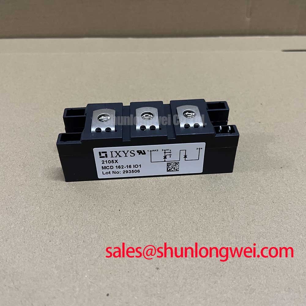
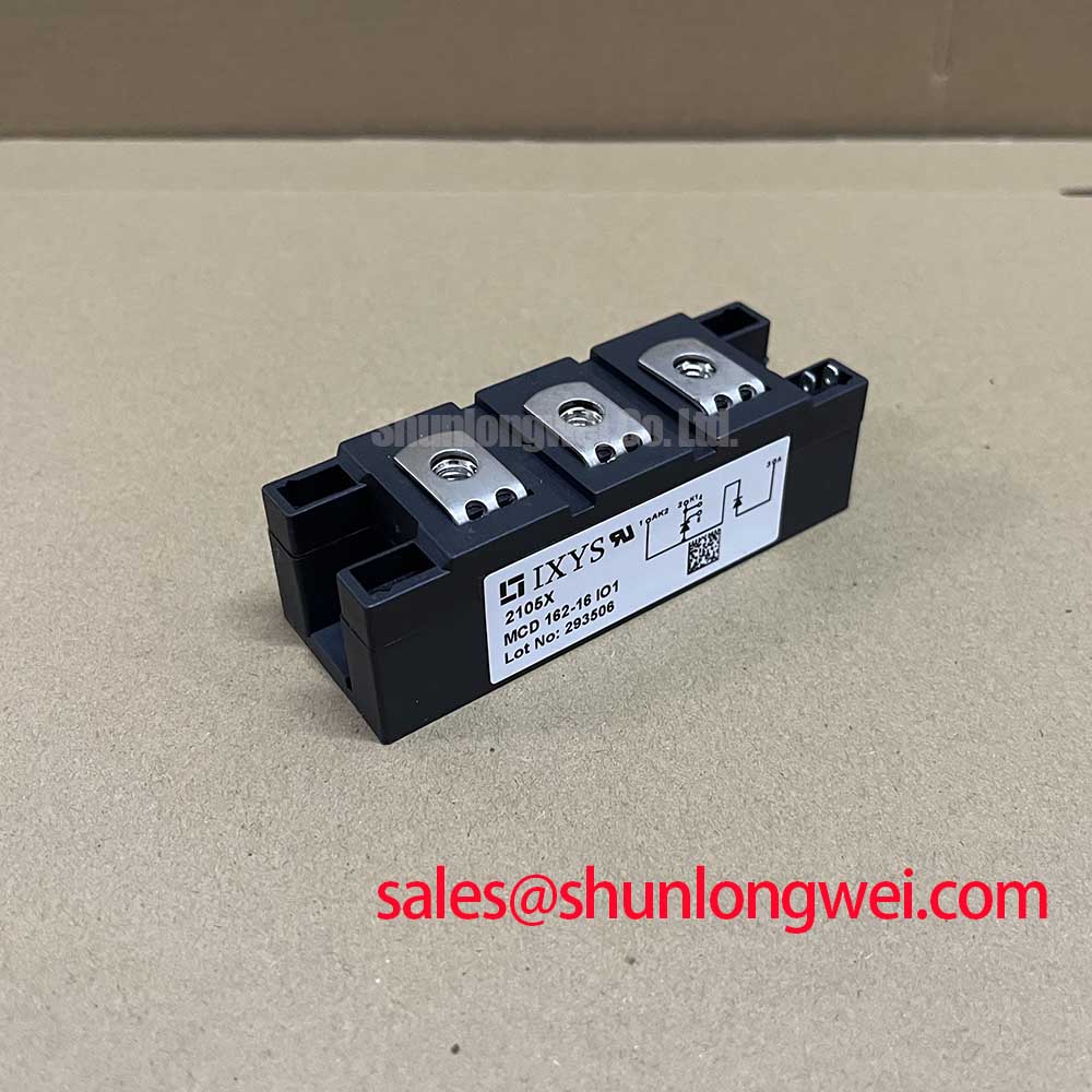
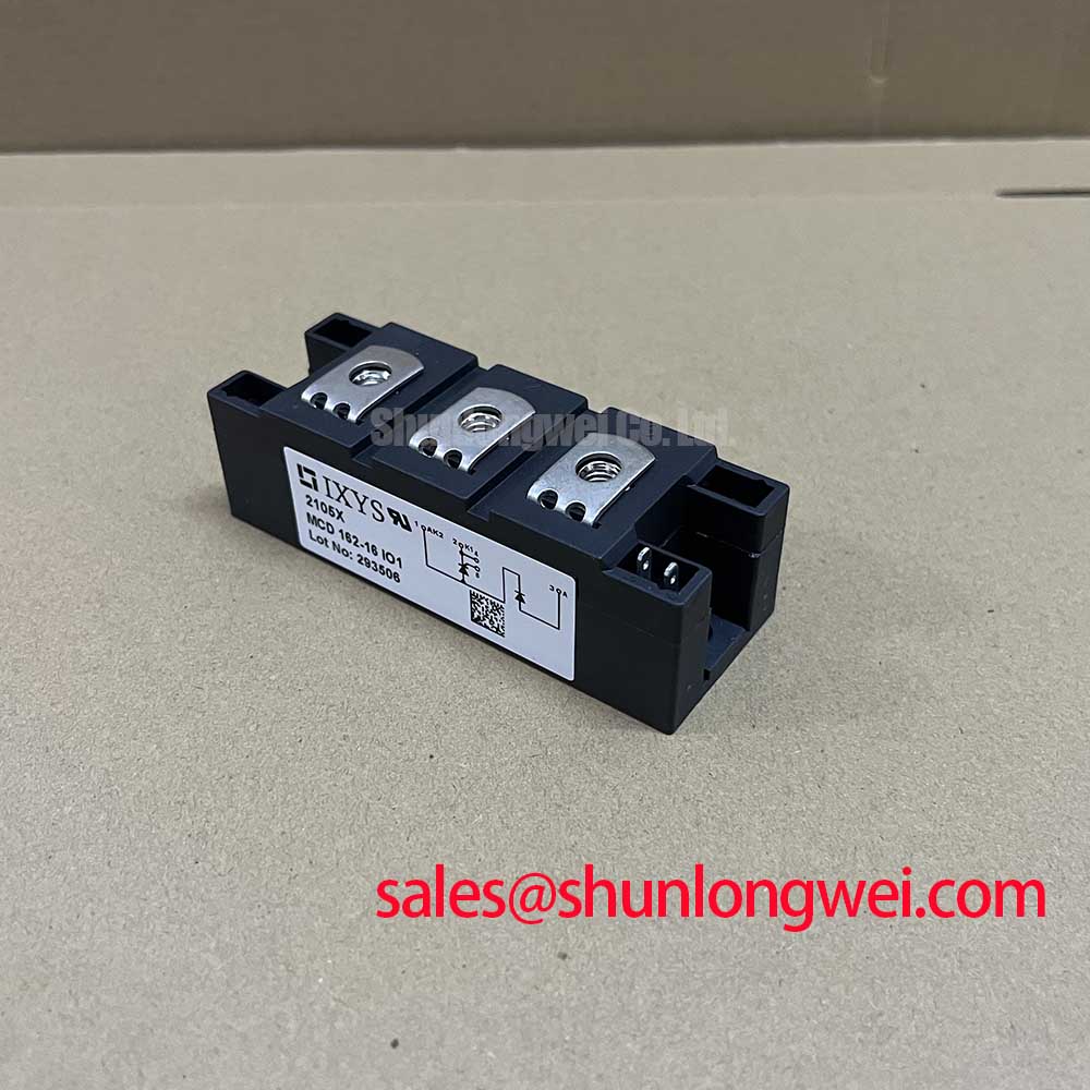
With the circuit isolated and stored energy discharged, compare the installed module’s terminal markings and mounting footprint with the equipment drawing before evaluating MCD162-16IO1 as a replacement. This IXYS thyristor/diode module has a supplied factory voltage rating of 1600 V, a supplied current rating of 165 A, and a TO-240AA package. These are Official Specification values; they do not, by themselves, establish fault withstand, surge capability, or interchangeability in an assembled system.
A semiconductor fuse should be checked against the thyristor’s permitted short-duration stress, not selected from the 165 A rating alone. During a prospective short circuit, both the current peak and the energy passed before clearing matter. The equipment engineer should obtain the applicable MCD162-16IO1 datasheet surge and I²t limits, then compare them with the fuse manufacturer’s total clearing I²t at the installation’s prospective fault current and supply voltage. The supplied product parameters do not include those withstand limits, so a claim of damage-free fault clearing would be unsupported.
| Coordination item | Basis for evaluation |
|---|---|
| Module voltage rating | 1600 V, Official Specification |
| Module current rating | 165 A, Official Specification; confirm the datasheet test conditions before comparing operating current |
| Module surge and I²t limits | Obtain the applicable IXYS datasheet values and their junction-temperature conditions |
| Fuse clearing performance | Use the proposed fuse’s published total clearing data for the actual fault conditions |
Terminal connections are part of that assessment. Record the existing cable or busbar order, check the equipment schematic against the module’s terminal identification, and inspect mating surfaces before reassembly. The TO-240AA package designation is useful for an initial mechanical check, but it does not replace a dimensional drawing or terminal map. Mounting torque should be taken from the applicable module documentation and the equipment’s fastener specification; no torque value is established by the supplied parameters.
For a repair-material comparison, TT570N16 can be examined alongside the installed device, but its circuit configuration, terminal layout, mounting arrangement, drive requirements, and fault ratings must be checked independently. A matching voltage class is not proof of a drop-in replacement.
MCD162-16IO1 Operational Boundaries: Surge Current and Reapplication of Voltage
A motor soft starter can impose a brief current demand that differs substantially from its established running condition. For MCD162-16IO1, evaluate that demand against the datasheet’s stated nonrepetitive surge-current rating, including the specified waveform, pulse duration, and starting junction temperature. The supplied 165 A rating cannot be substituted for a surge rating, and no numerical surge limit is available in the supplied product parameters.
Keep the event sequence visible when investigating a trip. Capture the current waveform, note whether the event followed a cold start or repeated attempts, and compare the measured pulse with the manufacturer’s applicable conditions. A nonrepetitive rating should not be treated as permission for repeated starts without checking the thermal state between events. Before reverse voltage is reapplied, designers should verify the relevant recovery and junction-temperature limits in the full datasheet and confirm them against the equipment’s measured waveforms.
Mounting also affects the thermal conditions behind a surge assessment. Check that the heatsink contact area is clean and flat, apply thermal interface material according to the module and equipment instructions, and tighten fasteners in the specified sequence. 💡 Pro Tip: Do not reuse an assumed mounting torque when the replacement module’s installation instructions have not been checked.
For a high-voltage three-phase motor solid-state soft starter, this is a compatibility evaluation rather than an application guarantee. The engineer still needs to establish the actual line voltage, starting-current profile, cooling arrangement, and bypass-contactor sequence before judging whether the module’s documented limits fit the equipment.
Transient Dynamics: Commutation and Terminal-Loop Layout
MCD162-16IO1 is identified here as a thyristor/diode module. A request for diode peak reverse-recovery current or diode softness data should therefore be tied to a confirmed circuit diagram and the relevant datasheet entry, not inferred from the product category. The supplied parameters do not establish an Irrm or trr value. In a controlled rectifier or AC switching circuit, inspect the actual commutation path and associated devices before assigning a measured transient to this module.
At the bench, compare voltage across the relevant terminals with phase current and gate-command timing during a controlled test. A voltage spike can be influenced by wiring inductance, current transfer between devices, or the surrounding suppression network; a single waveform does not identify one cause. As a Design Consideration, keep the high-current connection loop compact to reduce inductive overshoot, then verify peak voltage against the module’s 1600 V rating under the system’s operating conditions. Gate wiring should also be checked against the equipment drawing so that power-current paths do not disturb the firing signal.
If another controlled semiconductor, such as TT500N18KOF, appears elsewhere in the power circuit, assess its gate supply and commutation timing as a separate device. Its presence does not establish the terminal functions or firing requirements of MCD162-16IO1. Likewise, heavy-copper PCB construction is background for high-current trace design, not evidence that a particular board trace is suitable for this module’s circuit current.
Related guidance on switching-loop behavior appears in Unlocking Efficiency in Industrial Drives. It discusses IGBT technology, so its device-specific behavior and ratings should not be transferred to this thyristor/diode module. For MCD162-16IO1, use the confirmed thyristor documentation and measurements from the assembled equipment.
MCD162-16IO1 Thermal and Electrical Integration: Firing Angle and Power Quality
In a phase-controlled circuit, changing the firing angle changes the portion of each AC half-cycle delivered to the load. An earlier firing command generally allows more of the waveform through; a later command reduces the delivered voltage and changes current shape. The resulting power factor and harmonic content depend on the complete circuit and load, not on the module’s 1600 V and 165 A ratings. A universal transfer curve for this product would therefore be misleading without the equipment topology and operating measurements.
When evaluating a soft starter, compare commanded firing with measured phase voltage and current through the starting interval. Check that the gate pulse reaches the intended thyristor terminal and that the observed conduction follows the control sequence. If conduction differs between phases, examine gate timing, connections, load conditions, and the power path before attributing the behavior to the module. Gate-trigger current and voltage limits must come from the applicable datasheet; they are not present in the supplied product parameters.
Thermal verification should use the actual duty cycle. Record heatsink temperature and current during the start sequence and after the intended bypass transition, if the equipment uses one. Repeated starts and extended phase-controlled operation can produce different heating from steady bypassed operation. Any derating decision should be based on the manufacturer’s documented thermal limits and the measured installation conditions, rather than a margin assumed from the package or headline current rating.
Finally, check the terminal map, heatsink fit, gate-drive compatibility, fuse coordination, and measured operating waveforms as separate acceptance items. That approach keeps replacement assessment tied to the assembled equipment while preserving the distinction between the module’s Official Specification values and system-level design decisions.